Supercharge Your Innovation With Domain-Expert AI Agents!

Image pickup apparatus with foreign object removal capabilities

a pickup apparatus and foreign object technology, applied in the field of image pickup apparatus, can solve the problems of large amount of energy required, complicated vibration mode, and degraded image appearan

Inactive Publication Date: 2007-05-10
CANON KK
View PDF32 Cites 20 Cited by
  • Summary
  • Abstract
  • Description
  • Claims
  • Application Information

AI Technical Summary

Benefits of technology

[0012] At least one exemplary embodiment is directed to an image pickup apparatus capable of removing a foreign object (e.g., dust), on an optical member arranged in the optical axis for image taking in an efficient manner with a small amount of electric power.

Problems solved by technology

This results in a degraded appearance of the image.
Additionally, while the lens is interchanged, dust or other objects can enter a camera body from an opening of a lens mount and adhere to the camera components.
However, in order to remove the foreign object from the dustproof curtain, it is necessary to shake the foreign object off the dustproof curtain by application of a force larger than adhesion of the foreign object in the optical axis, and as a result, a large amount of energy is required.
Additionally, according to the above technique, since the dustproof curtain is vibrated by being displaced along the optical axis, if the shape of the dustproof curtain is not circular, it is known that the vibration mode is complicated and vibration efficiency is decreased.
Therefore, arranging the circular dustproof curtain within the image pickup apparatus is unfavorable in terms of layout.
This produces problems, such as an increase in the size of the image pickup apparatus, an inefficient layout therein.
At the same time, since the above technique requires a special component (namely the dustproof curtain) arranged in the optical axis for image taking, transmittance of the light beam for image taking is reduced, and as a result, the technique is unfavorable in terms of optical function or optical performance, in addition to inefficiency in layout.
Furthermore, a large amount of electric power is necessary for vibration of the dustproof curtain, which has a large size with respect to the effective light beams.

Method used


Image

  • Image pickup apparatus with foreign object removal capabilities
  • Image pickup apparatus with foreign object removal capabilities
  • Image pickup apparatus with foreign object removal capabilities

Examples


Embodiment Construction

[0026] The following description of at least one exemplary embodiment is merely illustrative in nature and is in no way intended to limit the invention, its application, or uses.

[0027] Processes, techniques, apparatus, and materials as known by one of ordinary skill in the relevant art may not be discussed in detail but are intended to be part of the enabling description where appropriate.

[0028] Notice that similar reference numerals and letters refer to similar items in the following figures, and thus once an item is defined in one figure, it may not be discussed for following figures.

[0029] At least one exemplary embodiment of the present invention will be described in detail in accordance with the accompanying drawings.

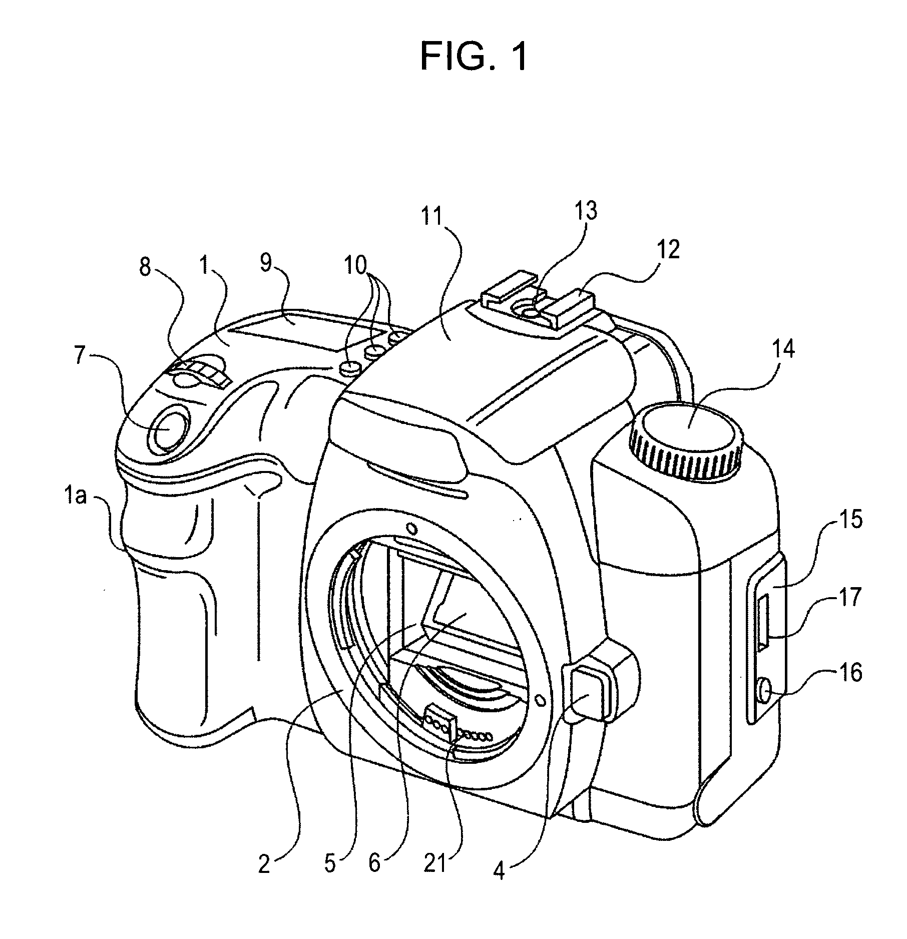
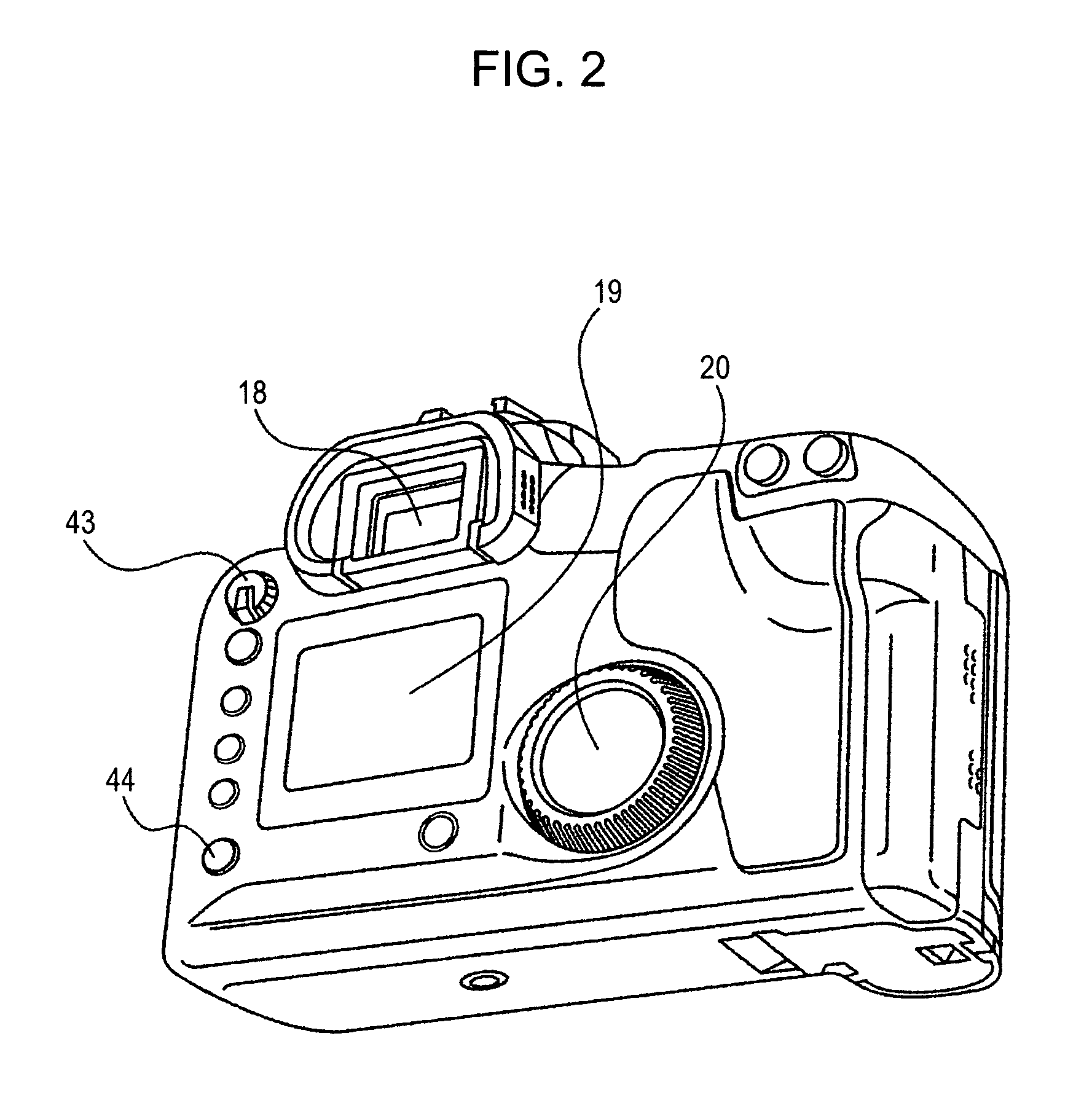
[0030]FIGS. 1 and 2 show external views of a digital single-lens reflex camera according to an exemplary embodiment. More specifically, FIG. 1 is a front perspective view of the camera with an image taking lens unit detached, and FIG. 2 is a rear perspective vi...


PUM


Abstract

At least one exemplary embodiment is directed to an image pickup apparatus which includes an optical member that is vibrated in a direction substantially perpendicular to an optical axis to facilitate removal of particles (e.g., dust), where the vibration of the optical member is substantially isolated from an image pickup element.

Description

BACKGROUND OF THE INVENTION [0001] 1. Field of the Invention [0002] The present invention relates to an image pickup apparatus and, in particular though not exclusively, to a technique of removing a foreign object from an optical member. [0003] 2. Description of the Related Art [0004] An image pickup apparatus that performs imaging by converting an image signal into an electrical signal, such as a digital camera, receives light with an image pickup element (e.g., a charge coupled device (CCD), a complementary metal oxide semiconductor (CMOS) device), converts a photoelectric conversion signal output from the image pickup element into image data, and records the image data on a recording medium (e.g., a memory card). In such an image pickup apparatus, an optical low-pass filter or an infrared cut filter is arranged adjacent to a subject with respect to the image pickup element, and when a foreign object (e.g., dust), adheres to a surface of the filter or a cover glass of the image pi...

Claims


Application Information

Patent Timeline
IPC IPC(8): H04N5/225
CPCG02B7/006G02B27/0006H04N5/2171H04N5/2254H04N23/811H04N23/55H04N23/672G03B19/12
Inventor KAIHARA, SHOJIYOSHII, HIROSHITSUKATANI, EIRIICHIKI, HIROKAZUHIRAI, FUTOSHIURAKAMI, TOSHIFUMIYAMAMOTO, HIDEAKINIWAMAE, YUUKI
Owner CANON KK
Features
  • R&D
  • Intellectual Property
  • Life Sciences
  • Materials
  • Tech Scout
  • Unparalleled Data Quality
  • Higher Quality Content
  • 60% Fewer Hallucinations
Learn More