
System, device, and method for over-current relays protecting motors

a relay and motor protection technology, applied in the direction of process and machine control, emergency protection arrangements, etc., can solve the problems of ac induction motors that fail the thermal memory test, electromechanical relay algorithms and 1sup>2/sup>t algorithms may not accurately track the used thermal capacity of ac motors under varying load, and achieve the effect of preventing motor overheating

Inactive Publication Date: 2007-05-10
SIEMENS ENERGY & AUTOMATION INC
View PDF18 Cites 11 Cited by
  • Summary
  • Abstract
  • Description
  • Claims
  • Application Information

AI Technical Summary

Benefits of technology

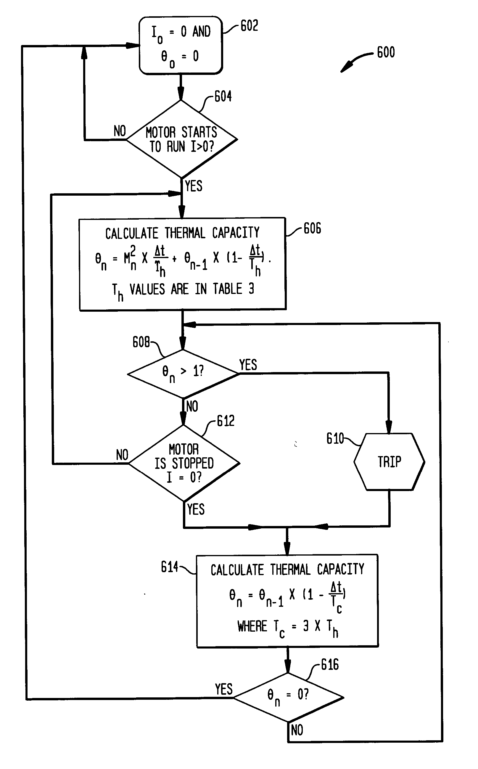
[0027] The present invention is a novel device, system, and method for an over-current relay protecting an induction motor comprising the following actions. The exemplary method may determine the current drawn by the motor. The method may also determine the state of the motor. The method may then calculate a used thermal capacity based on a first formula when the motor is in an active state. The method may also calculate the used thermal capacity based on a second formula when the motor is in an inactive state. Once the used thermal capacity attains a threshold the method may trip the relay, remove current from the motor, and prevent the motor from overheating.

Problems solved by technology

Therefore equation A1 does not simulate motor thermal dynamics for 0<M<1, which results in the algorithm not accurately tracking the used thermal capacity of AC motor under varying load.
From the analysis above, it is seen that both electromechanical relay algorithm and 12t algorithm may fail the thermal memory test and may not provide sufficient protection to AC induction motors.

Method used


Image

  • System, device, and method for over-current relays protecting motors
  • System, device, and method for over-current relays protecting motors
  • System, device, and method for over-current relays protecting motors

Examples


Embodiment Construction

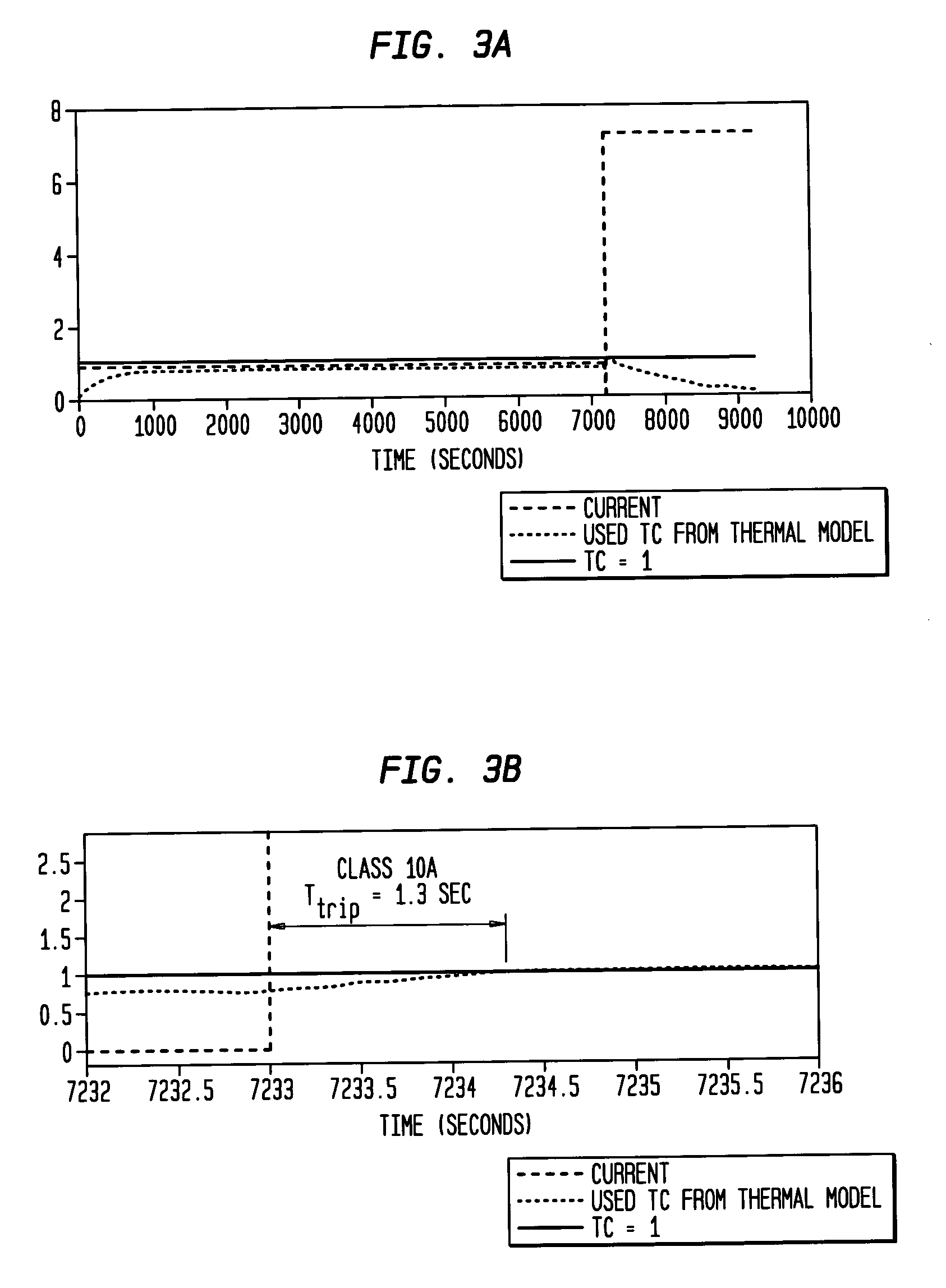
[0039] The present invention provides a control algorithm for solid-state relay protecting for induction motors. The algorithm utilizes a thermal model of an AC induction motors. The algorithm calculates used thermal capacity of the motors based on motor currents. The relay trips once the used thermal capacity reaches limit. This invention also provides a method to derive thermal time constants from motor thermal limit curves and IEC standard 60947-4-2 [3][4]. The thermal time constants may then used in the control algorithm 600 and 700 for calculation of the used thermal capacity. The resultant algorithm may then satisfy the requirements of motor thermal limit curves and IEC standard 60947-4-2 [3][4].

[0040] The following is a list of nomenclature used throughout the application. [0041] q heat input to a motor per second, its unit is Joules / sec, i.e., Watts, [0042] dt an infinitely small time interval in seconds, [0043]τ temperature rise in ° C., defined as the temperature differen...


PUM


Abstract

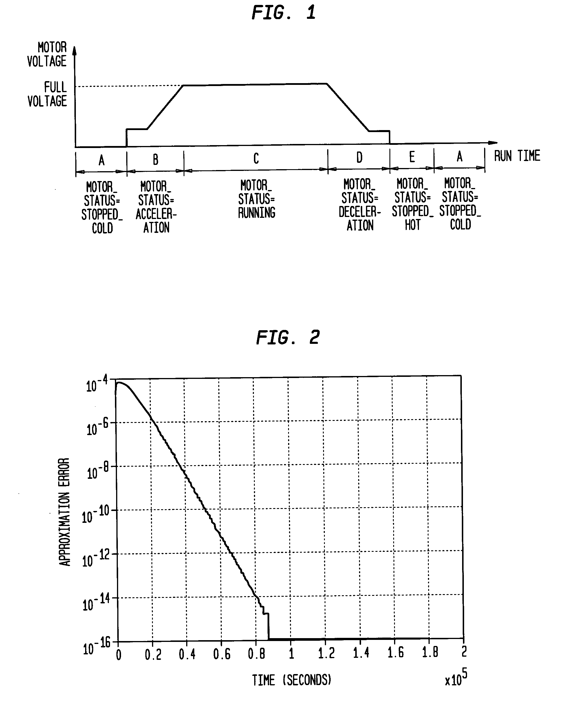
A system, method, and device for protecting an induction motor are disclosed. The exemplary system may have a module for determining the current drawn by the motor and a module for determining the state of the motor. The system may calculate a used thermal capacity based on a first formula when the motor is in an active state. The system also calculates the used thermal capacity based on a second formula when the motor is in an inactive state. When the used thermal capacity attains a threshold, the relay is tripped thus removing current to the motor and preventing motor from overheating. A method to derive thermal time constants from desired trip time limits (such as those defined by IEC standards or the thermal limit curves provided by motor manufacturers) is also presented. For example, the thermal time constants can then be used in tacking motor used thermal capacity throughout various motor states.

Description

CROSS REFERENCE TO RELATED APPLICATIONS [0001] This application is related to U.S. Provisional Patent Application No. 60 / 727,464 filed Oct. 17, 2005 entitled “Thermal model based DSP algorithm for solid-state over current relays protecting AC motors”, which is incorporated fully herein by reference.TECHNICAL FIELD [0002] The present invention relates to controls and protection for motors and more particularly, to a device, method, and system for determining the thermal properties of a motor. BACKGROUND INFORMATION [0003] In current practice, there are two types of control algorithms for solid-state over-current relays, namely, electromechanical relay algorithm [1][2] and 12t algorithm. The electromechanical relay algorithm is derived from the model of electromechanical relay using the following: For⁢ ⁢0<M<1⁢⁢t⁡(I)⁢ =trM2-1A1For⁢ ⁢M>1⁢⁢t⁡(I)=AMP-1+BA2[0004] Where [0005] t(I) is the reset time in Eq. (A1) or trip time in Eq. (A2) in seconds, [0006] M is the Iinput / Ipickup (I...

Claims


Application Information

Patent Timeline
IPC IPC(8): H02H7/08
CPCH02H6/00H02H7/085
Inventor BILAC, MARIOFAN, CHUNGOLOD, MIKHAIL
Owner SIEMENS ENERGY & AUTOMATION INC
Learn More