
Power tool

a technology of power tools and power supplies, applied in the field of power tools, can solve the problems of overheating of circuit boards, damage to components, and increase in temperature of transmission devices, so as to prevent the motor from overheating, reduce the temperature of motors, and improve the cooling effect.

Inactive Publication Date: 2020-04-30
MOBILETRON ELECTRONICS
View PDF0 Cites 1 Cited by
  • Summary
  • Abstract
  • Description
  • Claims
  • Application Information

AI Technical Summary

Benefits of technology

The present invention aims to provide a power tool with a good cooling effect to prevent the motor from overheating. The fan module is designed to cool the motor and remove the heat generated by it. This design ensures that the power tool operates efficiently and safely.

Problems solved by technology

If the motor is not effectively cooled, the components will be damaged.
For instance, a circuit board is overheated to be damaged.
If the temperature of the motor continues to rise, its thermal energy will be transmitted to the transmission, so that a temperature of the transmission will also rise, and there is a risk of overheating.
Therefore, how to effectively cool the motor of the power tool is one of the important problems to be solved.
Since the temperature of the motor will continuously rise when the motor continues in use, and the thermal energy of the motor will be transmitted to the hydraulic cylinder of the hydraulic pulse generator, so that a hydraulic oil temperature inside the hydraulic cylinder rises, thereby an oil seal will be destroyed and the hydraulic oil will be degraded.
For instance, a viscosity of the hydraulic oil will decrease due to the rise of the hydraulic oil temperature, and a fluidity will change, and even cause a leakage from the oil seal, affecting a sealing degree in the hydraulic cylinder, so that the conventional hydraulic pulse tool cannot output enough impact force.

Method used


Image

  • Power tool
  • Power tool
  • Power tool

Examples


Embodiment Construction

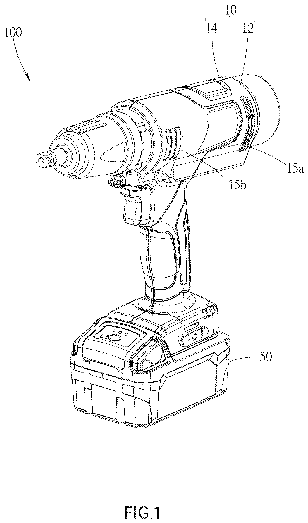
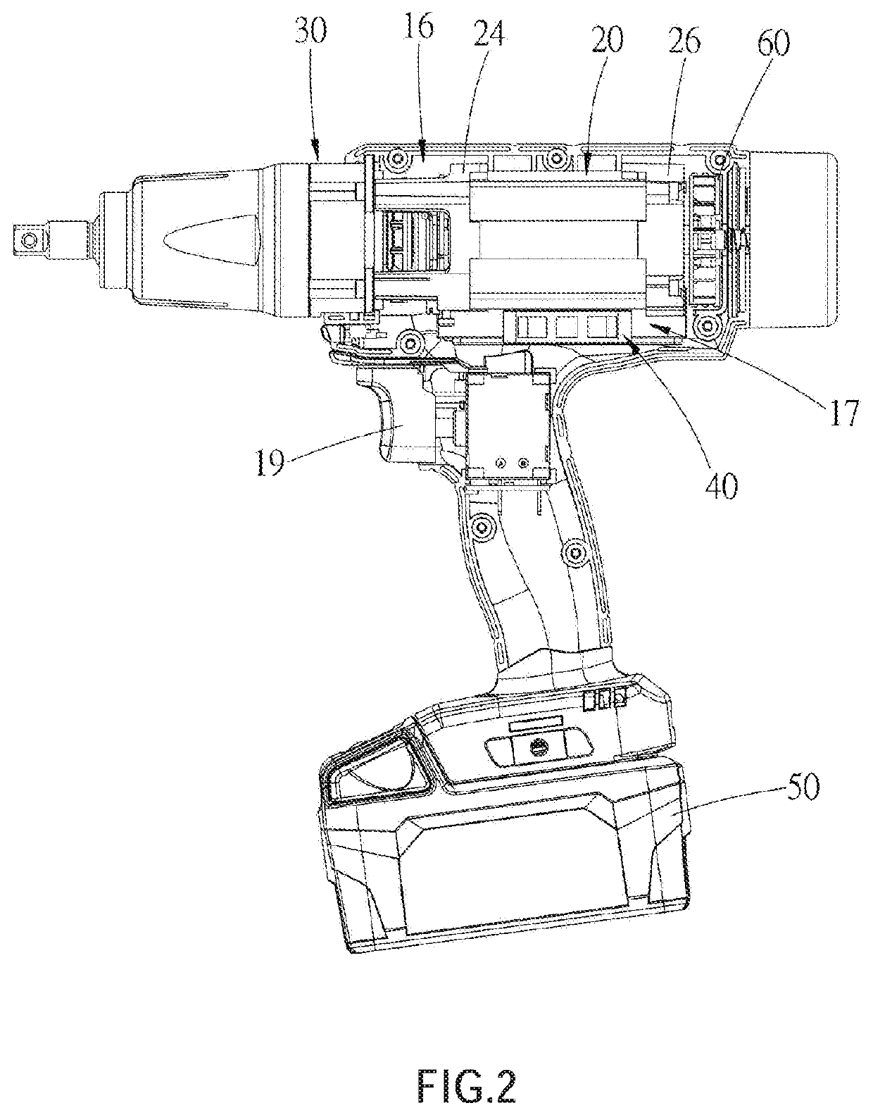
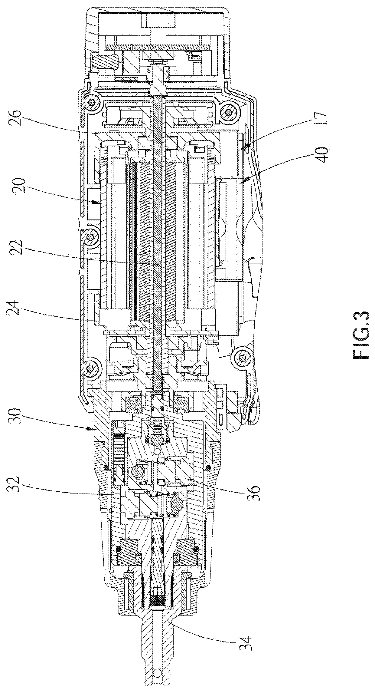
[0015]A power tool 100 according to an embodiment of the present invention is illustrated in FIG. 1 to FIG. 3, wherein the power tool 100 includes a casing 10, a motor 20, a transmission which is a hydraulic pulse generator 30 as an example, and a fan module 40.

[0016]In the current embodiment, the casing 10 includes a left-half casing 12 and a right-half casing 14, wherein the left-half casing 12 could match with the right-half casing 14 to form a receiving space for receiving the motor 20, the hydraulic pulse generator 30, and the fan module 40. In addition, a plurality of vents 15a, 15b are disposed on the casing 10, so that when the fan module 40 is in operation, an airflow could be guided into or out of the casing 10 via the vents 15a, 15b. Moreover, in the current embodiment, the casing 10 has a motor receiving portion 16 and a holding portion 18, wherein a space within the motor receiving portion 16 is adapted to receive the motor 20 and the hydraulic pulse generator 30. An ou...


PUM


Abstract

A power tool includes a casing having a motor receiving portion and a holding portion, a motor disposed in the motor receiving portion, a transmission disposed in the motor receiving portion, and a fan module disposed in the motor receiving portion. The holding portion is adapted to be held by a user. The motor has a rotatable shaft, a front side, and a back side opposite to the front side. The transmission is located on the front side of the motor and is connected to the rotatable shaft, and has an output shaft for being connected to a tool bit. The fan module has a driving motor and a fan blade. The driving motor is adapted to drive the fan blade to rotate. With such design, the fan module could cool the motor to remove the heat generated by the motor.

Description

BACKGROUND OF THE INVENTIONTechnical Field[0001]The present invention relates generally to a power tool, and more particularly to a power tool with a good cooling effect.Description of Related Art[0002]Typically, a conventional power tool includes a motor. When the motor continues to run, a temperature of the motor will continue to rise. If the motor is not effectively cooled, the components will be damaged. For instance, a circuit board is overheated to be damaged. In addition, in some applications, the conventional power tool further has a transmission connected to the motor. If the temperature of the motor continues to rise, its thermal energy will be transmitted to the transmission, so that a temperature of the transmission will also rise, and there is a risk of overheating. Therefore, how to effectively cool the motor of the power tool is one of the important problems to be solved.[0003]In addition, in a case that if the power tool is a conventional hydraulic pulse tool with a ...

Claims


Application Information

Patent Timeline
IPC IPC(8): B25F5/00B25B21/02
CPCB25F5/008B25B21/02
Inventor HUANG, JUI-CHENWANG, SHIH-HAO
Owner MOBILETRON ELECTRONICS
Learn More