Load driving device

a driving device and load technology, applied in the direction of emergency protective circuit arrangement, emergency protection arrangement for limiting excess voltage/current, etc., can solve the problem of circuit not being reliably protected, circuit fet tb>101/b> may be broken or burned, so as to prevent erroneous overcurrent detection

Inactive Publication Date: 2007-05-10
YAZAKI CORP
View PDF6 Cites 35 Cited by
  • Summary
  • Abstract
  • Description
  • Claims
  • Application Information

AI Technical Summary

Benefits of technology

[0031] In the above configuration, when the diagnosing unit diagnoses the overcurrent detecting unit, the prohibiting unit disables the overcurrent judgment which is based on the output signal of the comparing unit. This makes it possible to prevent erroneous overcurrent detection caused by an inversion of the output signal of the comparing unit during a diagnosis.

Problems solved by technology

Proper protection cannot be given and the FET T101 may be broken or the lines may be burnt.
However, the conventional load driving device has the problem that the circuit cannot be protected reliably in the event of an overcurrent if an on-failure occurs in one or some of the FETs T102-T104.
If a failure occurs in those circuit elements and lines, the circuit protecting function may be lost.
Since the loss of the circuit protecting function does not appear immediately, a failure continues to exist for a long time once it occurs.
As a result, the circuit may not be protected in the event of an overcurrent accident though its probability of occurrence is low.

Method used


Image

  • Load driving device
  • Load driving device
  • Load driving device

Examples


first embodiment

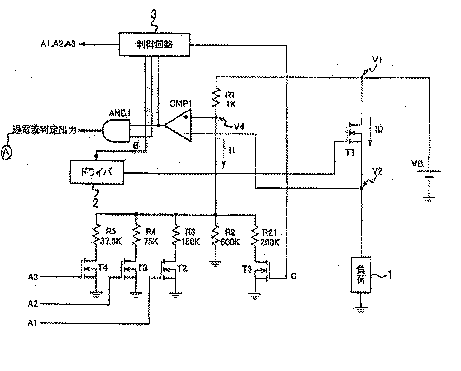
[0040] Embodiments of the present invention will be hereinafter described with reference to the drawings. FIG. 1 is a circuit diagram showing the configuration of a load driving device having a self-diagnosing function according to the invention.

[0041] As shown in FIG. 1, this load driving device is provided with a series circuit of a battery VB, a MOSFET T1 (semiconductor device; hereinafter referred to simply as “FET”), and a load 1 such as a lamp or a motor.

[0042] A driver (driving circuit) 2 is connected to the gate of the FET T1. When a drive signal is output from the driver 2, the FET T1 is turned on and the output voltage of the battery VB is applied to the load 1 to drive it.

[0043] The drain (first electrode; voltage: V1) of the FET T1 is grounded via a series circuit of resistors R1 and R2, and the connecting point (voltage V4) of the resistors R1 and R2 is connected to the plus-side input terminal of a comparator CMP 1. The source (second electrode; voltage: V2) of the F...

second embodiment

[0068] More specifically, in the load driving device the resistor R6 is provided between the source of the FET T1 and the minus-side input terminal of the comparator CMP1 and a series circuit of the resistor R7 and the FET T6 is provided between one end of the resistor R6 and the ground. The gate of the FET T6 is connected to the source of the FET T5.

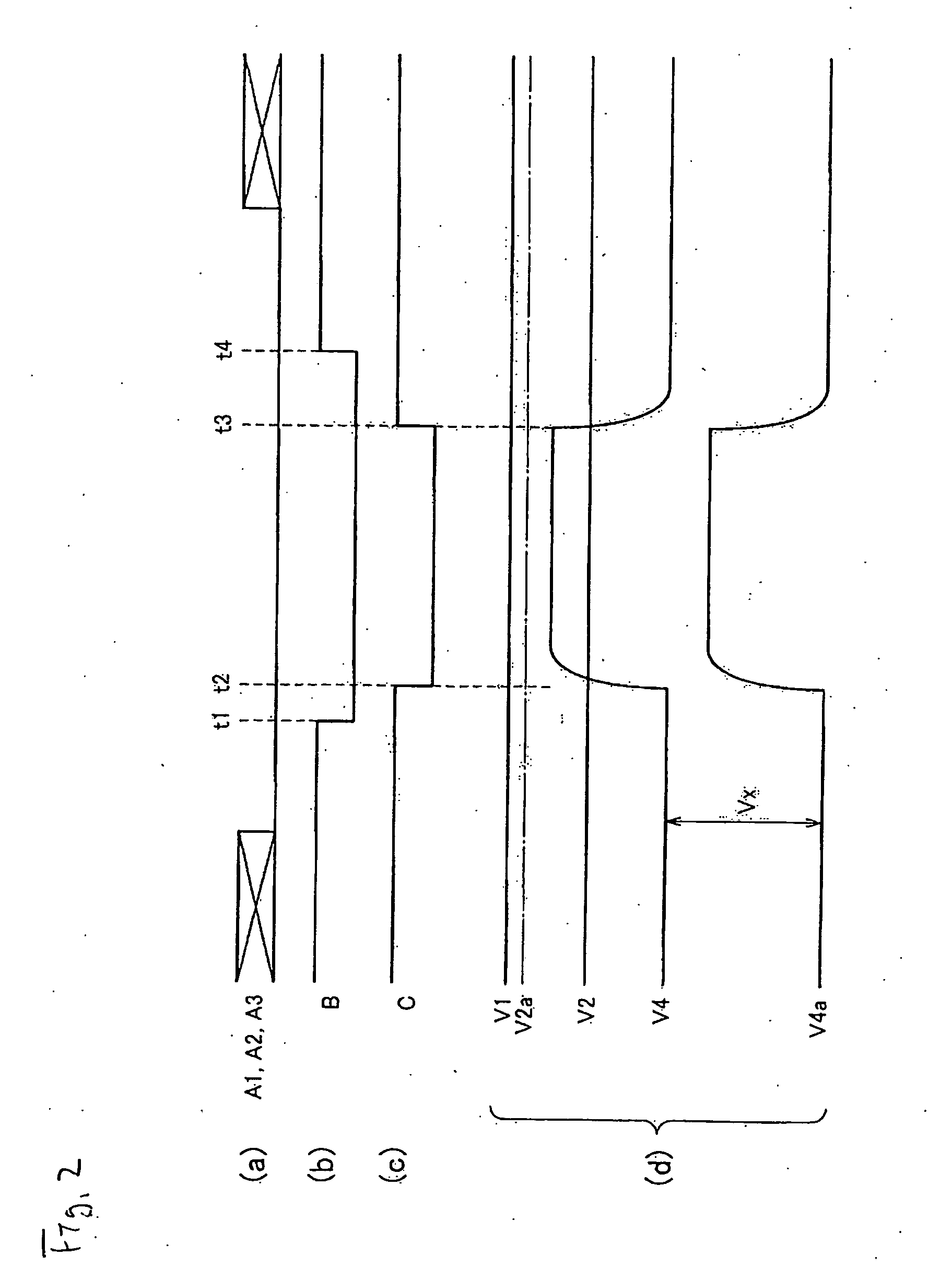
[0069] Next, the operation of the second embodiment will be described. In an ordinary state, the load driving device according to the second embodiment operates in the same manner as that according to the first embodiment. A diagnostic operation will be described below with reference to a timing chart of FIG. 4.

[0070] In a diagnostic operation, the level of the control signal B is changed to “L” at time t1, whereby the level of the output signal of the AND circuit AND1 is fixed to “L.” A control signal C is input to the gate of the FET T5 at time t2, whereby the FET T5 is turned off. As a result, the voltage V4 increases as in the cas...

third embodiment

[0075] The operation of the third embodiment will be described with reference to a timing chart of FIG. 6. The example of FIG. 6 is the same as the examples of FIGS. 2 and 4 in that a diagnostic operation is performed in a state that the control signals A1-A3 are at the L level and that in the period from time t1 to t4 the control signal B is set to the L level to fix the output level of the AND circuit AND1 to “L.”

[0076] The level of the control signal C is changed from “L” to “H” at time t2, whereby the FET T6 is turned on, whereupon a current flows through the resistor R6 and a voltage drop occurs there.

[0077] The resistance values of the resistors R6 and R7 are set so that the magnitude of the voltage drop (V2-V3) is somewhat larger than the standard judgment voltage (V1-V4). As a result, if the overcurrent detection circuit is functioning normally, in the period from t2 to t3 a relationship V34 is established and hence the output signal of the comparator CMP1 is inverted. The ...


PUM


Abstract

A load driving device for controlling a driving and a stop of a load through on/off switching of a semiconductor device under the control of a driving circuit, includes an overcurrent detecting unit that compares, with a prescribed judgment voltage, an inter-electrode voltage which is generated when a current flows between a first electrode and a second electrode of the semiconductor device, and judges that an overcurrent is flowing through the semiconductor device when the inter-electrode voltage is higher than the judgment voltage, and a diagnosing unit that performs a diagnosis as to whether the overcurrent detecting unit is operating normally in a state that the semiconductor device is a on-state. When the diagnosing unit judges that the overcurrent detecting unit is not operating normally, the diagnosing unit outputs an instruction signal for turning off the semiconductor device, to the driving circuit.

Description

BACKGROUND OF THE INVENTION [0001] The present invention relates to a load driving device with a function of interrupting a circuit in the event of an overcurrent. In particular, the invention relates to a load driving device with a self-diagnosing function of detecting a failure in an overcurrent detecting function. [0002] For example, in load driving devices for driving a load such as a lamp or a motor provided in a vehicle, a MOSFET as an electronic switch is provided between the battery and the load and the driving and the stop of driving of the load are controlled by turning on or off the MOSFET. They are provided with an overcurrent detecting function to protect circuit components of the load, MOSFET, and electrical wires when an overcurrent flows through the load by detecting it immediately. [0003]FIG. 7 shows an exemplary circuit which is known as such a load driving device having an overcurrent detecting function. [0004] As shown in FIG. 7, this load driving device is provi...

Claims


Application Information

Patent Timeline
Patent Type & Authority Applications(United States)
IPC IPC(8): H02H3/08
CPCG01R19/16571G01R35/00H02M1/32H02M3/156H03K17/0822H02H1/043H02H3/006H02H3/08H02H7/20H02H9/02
Inventor OHSHIMA, SHUNZOU
Owner YAZAKI CORP
Why Eureka
Try Eureka