Circuit for charging protection with enhanced overcurrent protection circuitry

a protection circuit and circuit technology, applied in the direction of safety/protection circuits, emergency protection circuit arrangements, emergency protection devices, etc., can solve the problems of short circuit, damage to battery, damage to devices, etc., to speed up the fuse meltdown and increase the current flowing through the fuse

Inactive Publication Date: 2007-05-10
BENQ CORP
View PDF7 Cites 28 Cited by
  • Summary
  • Abstract
  • Description
  • Claims
  • Application Information

AI Technical Summary

Benefits of technology

[0008] It is therefore an objective of the present invention to provide a charging protection circuit with an overcurrent protection circuit to address the above-mentioned problems. The charging protection circuit comprises a fuse, an output and an overcurrent protector. The fuse has a first end and a second end. The first end of the fuse is coupled to a power supply. The se

Problems solved by technology

In the charging process, however, the charging devices may malfunction, or short-circuit, for many reasons, such as rust in a conducting metal, charging an out-of-spec battery, alternating the polarity of the battery, damaged battery circuits, and so forth.
The malfunction or short circuit pulls a large current from the power supply, and the excess charge current can damage the battery and even cause an explosion that destroys the device and could harm users.
Nevertheless, there are disadvantages to the above techniques.
One of the main drawbacks is that it takes time to melt down th

Method used


Image

  • Circuit for charging protection with enhanced overcurrent protection circuitry
  • Circuit for charging protection with enhanced overcurrent protection circuitry
  • Circuit for charging protection with enhanced overcurrent protection circuitry

Examples


Embodiment Construction

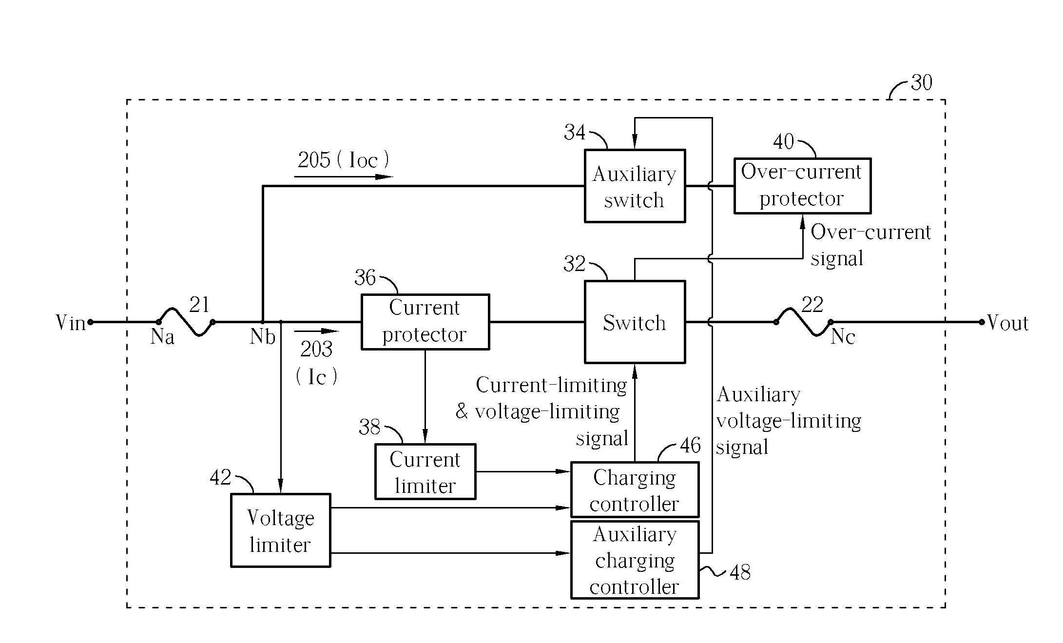
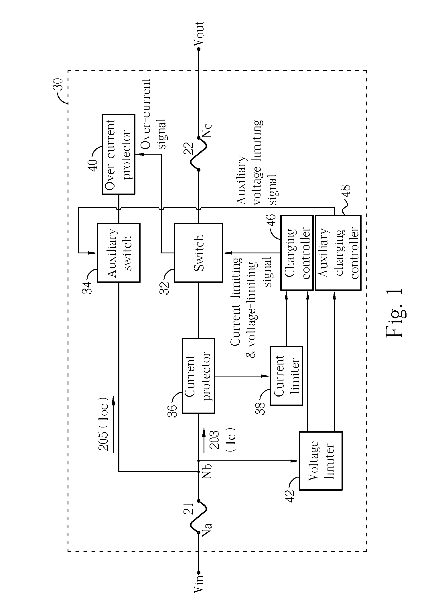
[0015] Please refer to FIG. 1. FIG. 1 is a diagram of a charging protection circuit 30. The charging protection circuit 30 comprises a fuse 21, a current detector 36, a switch 32, an auxiliary fuse 22, a current limiter 38, a charging controller 46, an auxiliary switch 34, an overcurrent protector 40, a voltage limiter 42, and an auxiliary charging controller 48. The first end of the fuse 20 is connected to a node Na and receives a current from a power supply. The second end of the fuse is connected to a node Nb, a branch 203, and a branch 205, and transmits the current from the power supply. The current detector 36, the switch 32, and the auxiliary fuse 22 are coupled at the branch 203. A charging current Ic flows through the branch 203 and the charging current is output to the battery at a node Nc, namely the output end of the charging protection circuit 30.

[0016] The switch 32 is used to control the charging current Ic. The current detector 36 measures the magnitude of the charg...


PUM


Abstract

A charging protection circuit with an overcurrent protector circuit takes input from a power supply, and provides output power to a power storage device, such as a battery. A fuse is connected between an input and an output of the charging protection circuit to protect the power storage device from a current spike, or overcurrent, that would damage the power storage device. When the overcurrent is above a threshold of the fuse, the fuse melts, effectively creating an open circuit and blocking the overcurrent from reaching the power storage device. To speed up the fuse meltdown, the overcurrent protector circuit is connected to the output of the fuse, and draws an extra current through the fuse when the overcurrent is detected.

Description

BACKGROUND OF THE INVENTION [0001] 1. Field of the Invention [0002] The present invention relates to a charging protection circuit, and more specifically, to a charging protection circuit with a circuit-level enhanced overcurrent protection mechanism. [0003] 2. Description of the Prior Art [0004] With the development and progress of electronic technologies, the size and weight of electronic devices such as mobile phones, personal digital assistants (PDA), digital cameras, portable media players, portable computers, and so on, have been greatly reduced, making them easily portable. Most of these portable devices are powered by batteries, and therefore battery chargers are essential to keeping these devices functioning. One example of such a charger is a mobile phone charging base, which converts alternating current (AC) into direct current (DC) for charging the batteries. [0005] In the charging process, however, the charging devices may malfunction, or short-circuit, for many reasons...

Claims


Application Information

Patent Timeline
IPC IPC(8): H02H5/04
CPCH01H85/46H01H2085/466H02H3/087H02H3/202H02J7/0031H02J2007/0039H02J7/00304H02J7/00308
Inventor HUANG, CHUN-WEILIN, CHIEN-TANGYANG, SHUN-CHUAN
Owner BENQ CORP
Why Eureka
Try Eureka