Shift register

a technology of shift register and shift register, which is applied in the direction of information storage, static storage, digital storage, etc., can solve the problems of deterioration of pull-down switching device, increase stage size and manufacturing cost, and achieve the effect of reducing the number of switching devices, reducing size and manufacturing costs

Active Publication Date: 2007-05-10
LG DISPLAY CO LTD
View PDF5 Cites 97 Cited by
  • Summary
  • Abstract
  • Description
  • Claims
  • Application Information

AI Technical Summary

Benefits of technology

[0017] An object of the present invention is to provide a shift register having a reduced n

Problems solved by technology

Hence, the pull-down switching device connected to the disabling node is kept turned on much longer than the pull-up switching device causing deteri

Method used


Image

  • Shift register
  • Shift register
  • Shift register

Examples


Embodiment Construction

[0075] Reference will now be made in detail to exemplary embodiments of the present invention, examples of which are illustrated in the accompanying drawings. Wherever possible, the same reference numbers will be used throughout the drawings to refer to the same or like parts.

[0076] In embodiments of the present invention, each of the switching devices, for example the pull-up switching devices and pull-down switching devices, may be any one of an N-type metal oxide semiconductor (MOS) transistor or a P-type MOS transistor. The exemplary embodiments of the present invention will hereinafter be described with N-type MOS transistors as switching devices.

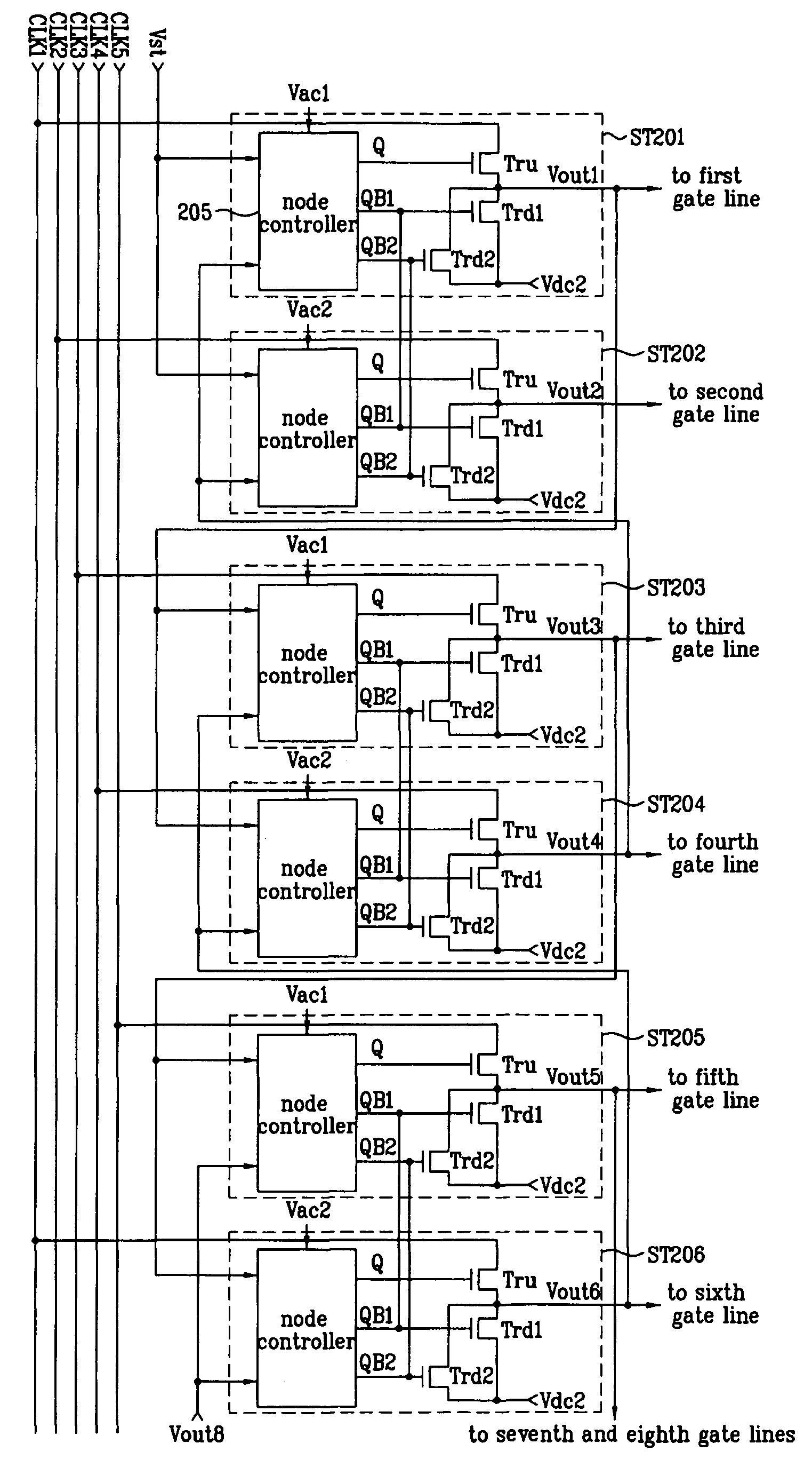
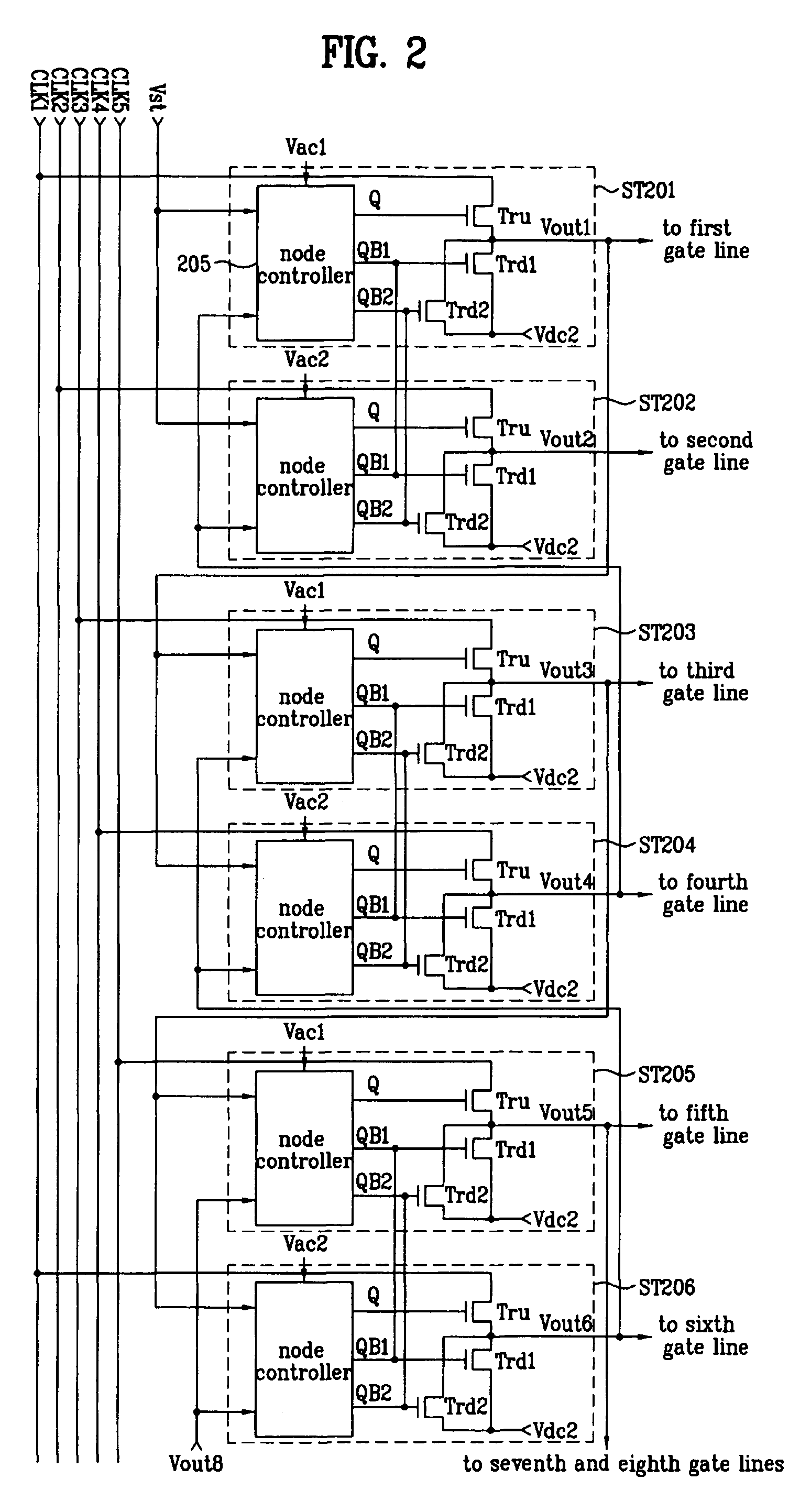
[0077]FIG. 2 is a schematic view of a first exemplary shift register according to an embodiment of the present invention. Referring to FIG. 2, a shift register includes a plurality of stages ST201, ST202, ST203, . . . for driving a plurality of gate lines, each one of the gate line being a conductive line. Each of the stages ST201, S...


PUM


Abstract

A shift register includes first and second stages for sequentially outputting scan pulses to drive first and second gate lines. One of the first and second stages includes a pull-up switching device connected to an enabling node of the one of the first and second stages; a first pull-down switching device connected to a first disabling node of the one of the first and second stages; a second pull-down switching device connected to a second disabling node of the one of the first and second stages; and a node controller. The node controller of the first stage controls the logic state of each of the enabling node of the first stage, the first disabling node of the first stage and the first disabling node of the second stage. The node controller of the second stage controls the logic state of each of the enabling node of the second stage, the second disabling node of the second stage and the second disabling node of the first stage.

Description

[0001] This application claims the benefit of Korean Patent Application Nos. 2005-0101680, filed on Oct. 27, 2005, and 2006-0059125, filed on Jun. 29, 2006, and 2006-0094004, filed on Sep. 27, 2006, all three of which are hereby incorporated by reference in their entirety. BACKGROUND OF THE INVENTION [0002] 1. Field of the Invention [0003] Embodiments of the present invention relate to a liquid crystal display (LCD) device, and more particularly, to a shift register for an LCD device. Embodiments of the present invention are suitable for a wide scope of applications. In particular, an embodiment of the present invention is suitabe for providing a shift register with a reduced number of switching devices for low manufacturing costs. [0004] 2. Discussion of the Related Art [0005] In general, a liquid crystal display (LCD) device displays an image by generating an electric field through a liquid crystal material to control light transmittance. The LCD device includes a liquid crystal p...

Claims


Application Information

Patent Timeline
IPC IPC(8): G11C19/00
CPCG11C19/28
Inventor KIM, BINNKIM, HAECHO, HYUNGYOON, SOOCHOI, SEUNGCHUN, MINJANG, YONG
Owner LG DISPLAY CO LTD
Why Eureka
Try Eureka