Printed circuit board inspection system combining x-ray inspection and visual inspection

Active Publication Date: 2007-05-10
MIRTEC
View PDF8 Cites 4 Cited by
  • Summary
  • Abstract
  • Description
  • Claims
  • Application Information

AI Technical Summary

Benefits of technology

[0011] Thus, the present invention is devised to solve the above problem and an object of the present invention is to provide a circuit board inspection system combining an X-RAY inspection and a v

Problems solved by technology

Further, for the electronic components as well, since the integration degree becomes higher and he size becomes smaller, chances are grow much stronger that defects may occur unless much attention is paid in fabricating the printed circuit board or mounting the c

Method used


Image

  • Printed circuit board inspection system combining x-ray inspection and visual inspection
  • Printed circuit board inspection system combining x-ray inspection and visual inspection

Examples


Example

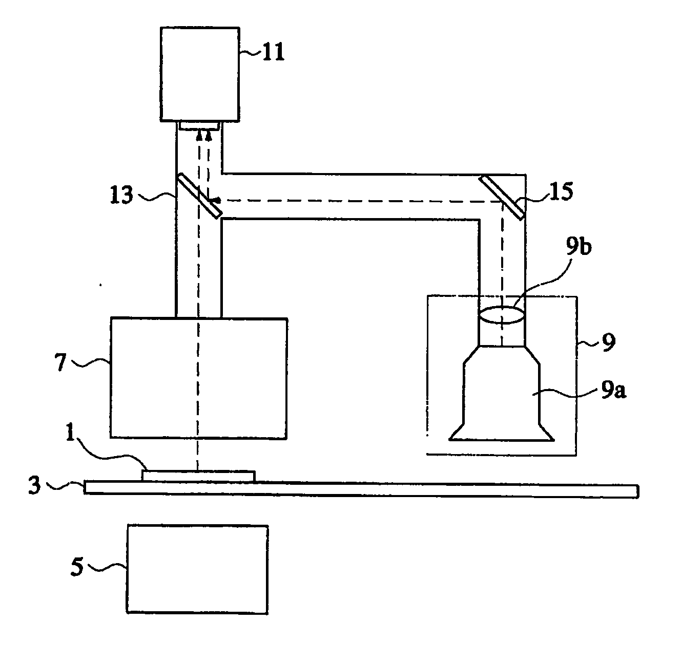
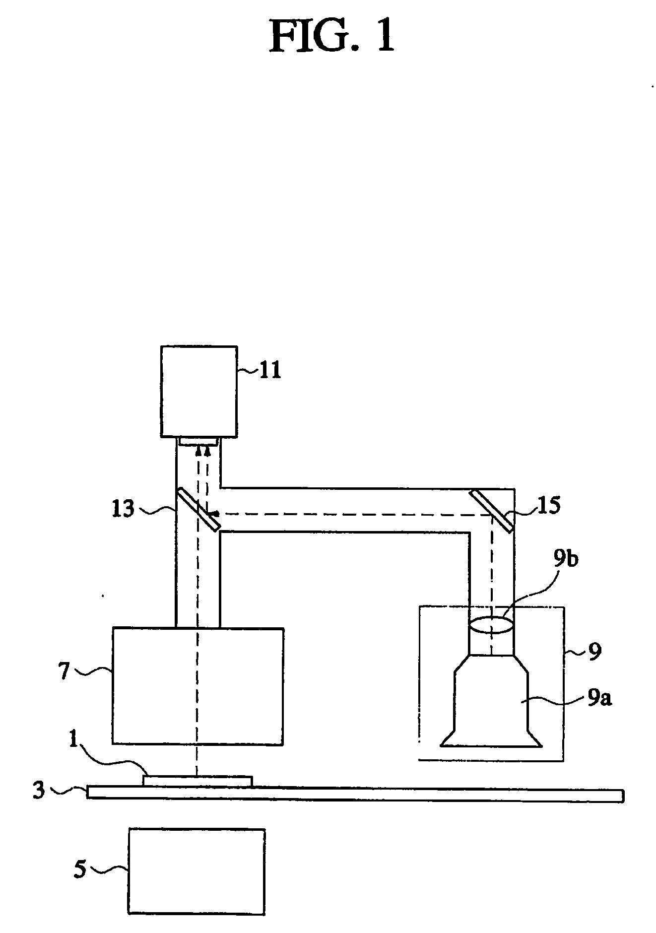
[0016] A configuration and an operation of an embodiment of the present invention will be described below with reference to the accompanying drawing, FIG. 1.

[0017] As shown in FIG. 1, an embodiment of the present invention comprises a transfer unit 3 that lands an inspected object 1 safely thereon and transfers the inspected object to a predetermined direction; a light generating unit 5 that is installed below the transfer unit 3 and emits a light having a predetermined wavelength toward the inspected object 1; a light amplifying unit 7 that is installed on the opposite side of the light generating unit 5 to convert and amplify a predetermined light that transmits the inspected object 1 into a visible light; an optical unit 9 that optically illuminates the inspected object 1 to create a visual image; and a camera 11 that receives an X-ray image amplified through the light amplifying unit 7 or the visual image by the optical unit 9 to obtain an image. Preferably, the light generatin...


PUM


Abstract

A circuit board inspection system combining an X-RAY inspection and a visual inspection comprises a transfer unit (3) that lands an inspected object (1) safely thereon and transfers the inspected object (1) to a predetermined position; a light generating unit (5) that is installed below the transfer unit (3) and emits a light having a predetermined wavelength to the inspected object (1); a light amplifying unit (7) that is installed on the opposite side of the light generating unit (5) to convert and amplify a predetermined light that transmits the inspected object (1) into a visible light; an optical unit (9) that optically illuminates the inspected object (1) to create a visual image; and a camera (11) that receives an X-ray image amplified through the light amplifying unit (7) or a visual image by the optical unit (9) to obtain information.

Description

BACKGROUND OF THE INVENTION [0001] 1. Field of the Invention p The present invention relates to a circuit board inspection system combining an X-RAY inspection and a visual inspection and, more particularly, a circuit board inspection system combining an X-RAY inspection and a visual inspection that is implemented such that an X-RAY image formed by transmitting an X-RAY source and a visual image projected optically is processed with one camera, thereby attempting to simplify the system. [0002] 2. Description of the Related Art [0003] Recently, as electronic devices have a tendency to be small, light and multi-functional, the integration degree of a printed circuit board and electronic components mounted thereon becomes rapidly improved. That is, the printed circuit board becomes multi-layered, and the patterns formed thereon become denser. Further, for the electronic components as well, since the integration degree becomes higher and he size becomes smaller, chances are grow much st...

Claims


Application Information

Patent Timeline
IPC IPC(8): G01B15/06G01N23/02G01N21/956G01N23/04
CPCG01N21/956G01N23/04
Inventor KIM, JONG-WONLEE, DONG-HYUNHONG, SEONG-CHEOL
Owner MIRTEC
Why Eureka
Try Eureka