Internal brace for distraction arthroplasty

a brace and distraction technology, applied in the field of distraction brace for distraction arthroplasty, can solve the problems of loss or decrease in medial or lateral joint space with associated tearing, methods other than bracing, and not encouraging replenishment or regeneration of articular cartilag

Inactive Publication Date: 2007-05-10
MANSPEIZER SHELDON
View PDF3 Cites 182 Cited by
  • Summary
  • Abstract
  • Description
  • Claims
  • Application Information

AI Technical Summary

Problems solved by technology

In both situations, the end result is that there is a loss or decrease in either the medial or lateral joint space with associated tearing or extrusion of the medial meniscus or lateral meniscus.
All

Method used


Image

  • Internal brace for distraction arthroplasty
  • Internal brace for distraction arthroplasty
  • Internal brace for distraction arthroplasty

Examples


Embodiment Construction

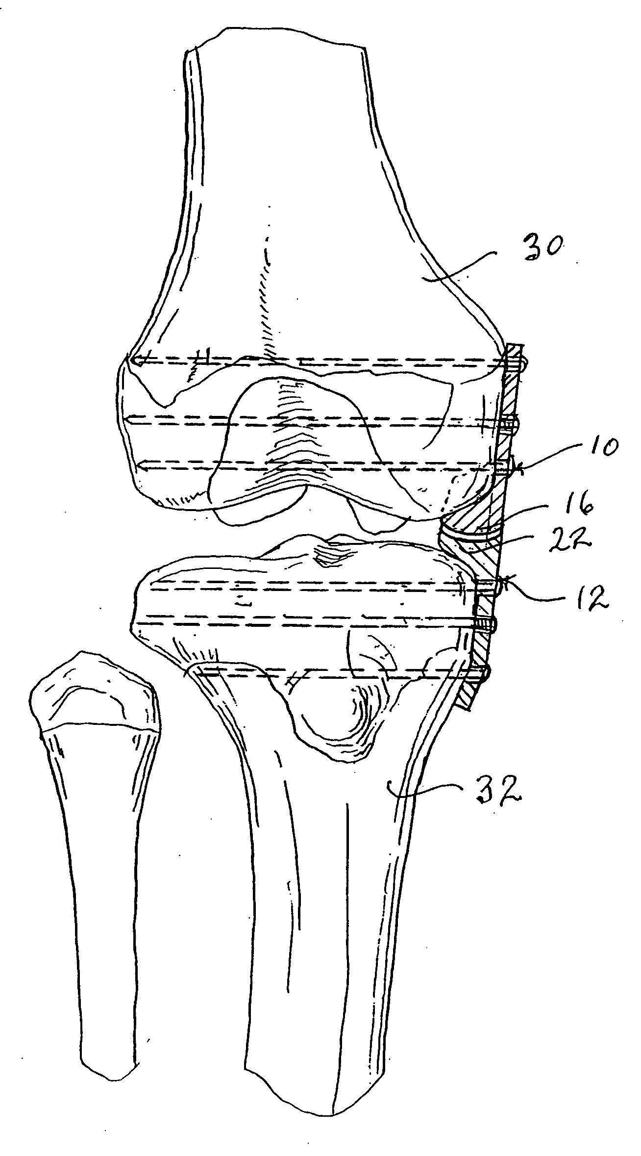
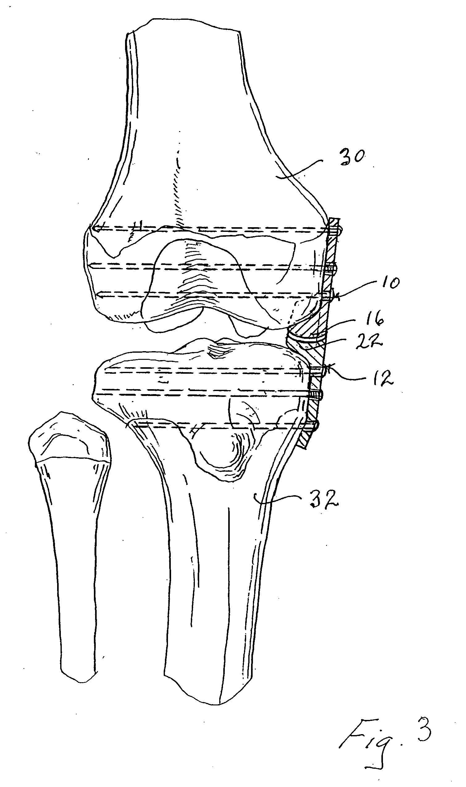
[0015] A brace according to the invention comprises a femoral component 10 and a tibial component 12. The femoral component 10 includes an elongated stem 14 tapering outwardly into a condylar protrusion 16 which has a convex lower surface 18.

[0016] The tibial component 12 includes an elongated stem 20 tapering outwardly into an upper tray 22 which includes a concave upper surface 24 to receive the mating convex lower surface 18 of the condylar protrusion 16 when the brace is installed. Each component includes holes 26 for attachment to the knee by means of screws.

[0017] Tray 22 of tibial component 12 is contoured to match the contour of the tibial plateau whereas the curvature of the condylar protrusion 16 of femoral component 10 should conform to the curvature of the condyle.

[0018]FIGS. 3 and 4 show the brace installed in the medial joint. Portions of the patient's femur 30 and tibia 32 are removed to receive the stems 14 and 20, respectively. The brace components 10 and 12 are ...


PUM


Abstract

A method for treating a patient suffering from osteoarthritis and an internal brace for distraction arthroplasty including femoral and tibial components which can be fixed to a patient's femur and tibia and which in combination distract or separate the knee joint without substantially hindering mobility of the knee.

Description

[0001] This patent application is a continuation of U.S. patent application Ser. No. 10 / 841,354, filed May 7, 2004, which claims priority pursuant to 35 U.S.C. § 119 from Provisional Patent Application Ser. No. 60 / 480,090 entitled “Internal Brace for Distraction Arthroplasty,” filed Jun. 19, 2003, the both disclosures are hereby incorporated by reference in their entirety.[0002] This invention relates to a brace for use with patients suffering from osteoarthritis in the knee. More particularly, the invention relates to an internal brace which can be fixed to a patient's femur and tibia and which distracts or separates the knee joint without substantially hindering mobility of the knee. BACKGROUND OF THE INVENTION [0003] The main radiological finding of a unicompartment osteoarthritis of the knee is the loss or decrease in the articular cartilage space. The secondary findings are spur formation and / or synovitis of the knee. The articular cartilage that is lost in the knee generally o...

Claims


Application Information

Patent Timeline
IPC IPC(8): A61B17/80A61F2/38A61B17/02
CPCA61B2017/0268A61F2/3836A61F2002/3895A61B2017/567
Inventor MANSPEIZER, SHELDON
Owner MANSPEIZER SHELDON
Why Eureka
Try Eureka