Air flow device incorporated into seat for a vehicle

Inactive Publication Date: 2007-05-17
DENSO CORP
View PDF5 Cites 26 Cited by
  • Summary
  • Abstract
  • Description
  • Claims
  • Application Information

AI Technical Summary

Benefits of technology

[0008] The present invention has been accomplished to solve the above problems of the prior art. An object of the present invention is to pro

Problems solved by technology

However, in the above conventional air flow device incorporated into a seat for vehicle use, a flow of air is sent into the vehicle passenger compartment from a large number of small holes formed in the seat skin.
Therefore, a large pressure l

Method used


Image

  • Air flow device incorporated into seat for a vehicle
  • Air flow device incorporated into seat for a vehicle
  • Air flow device incorporated into seat for a vehicle

Examples


Example

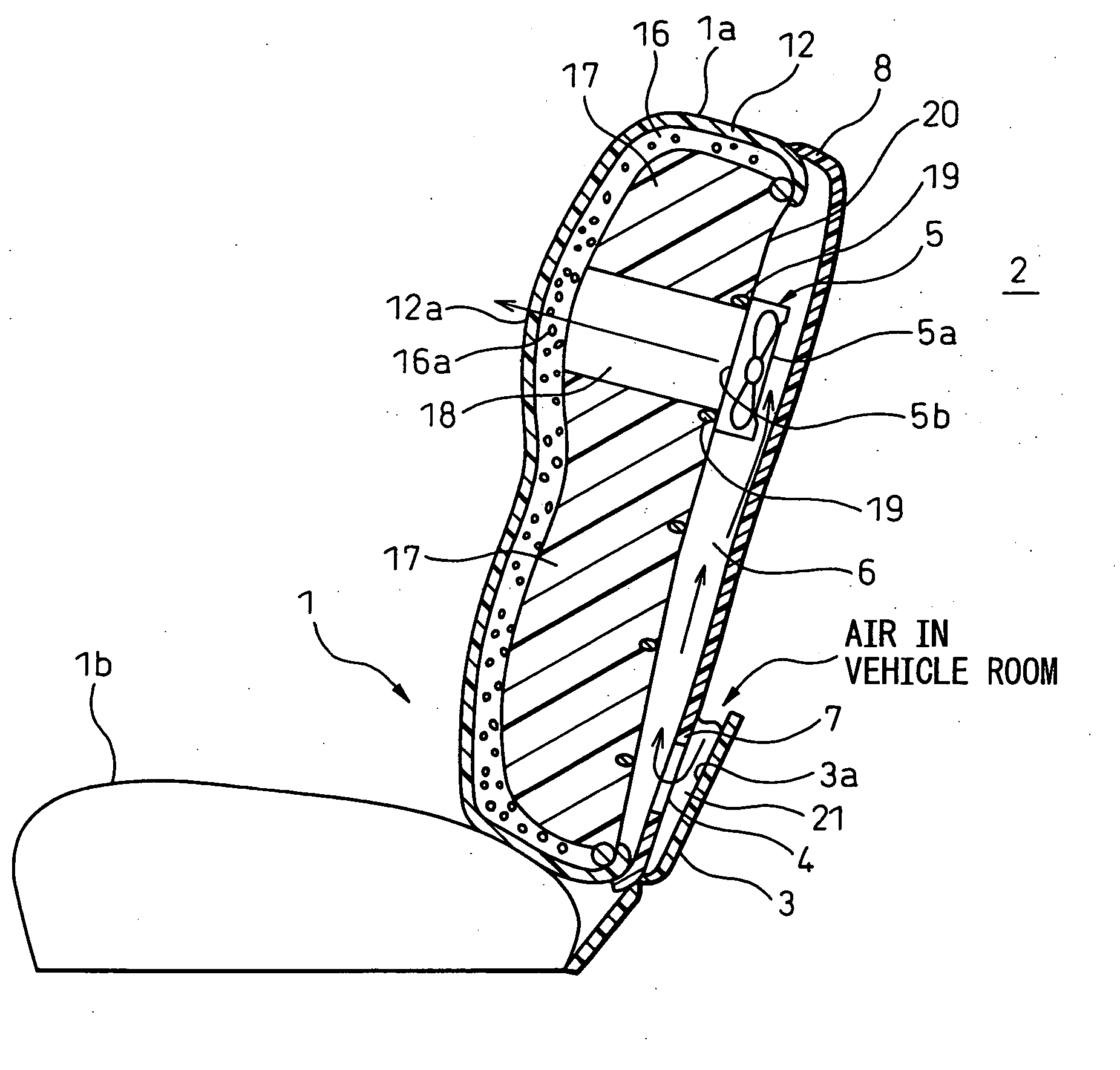
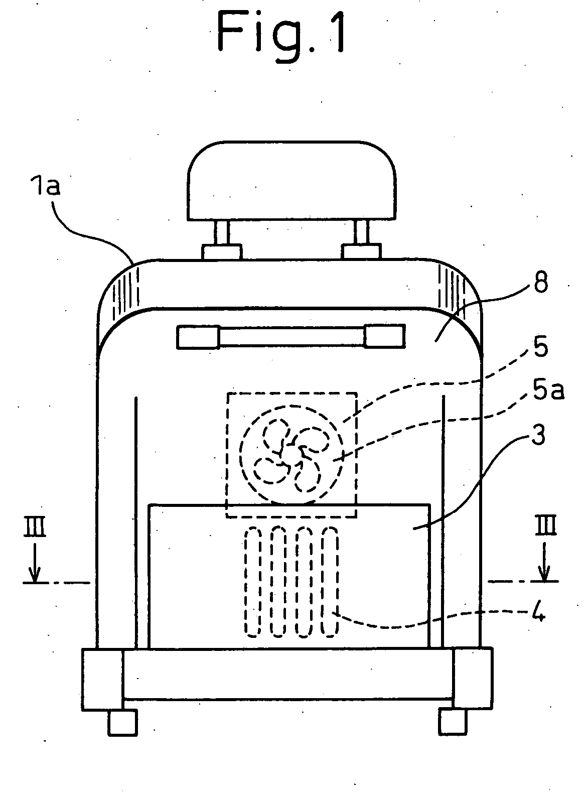
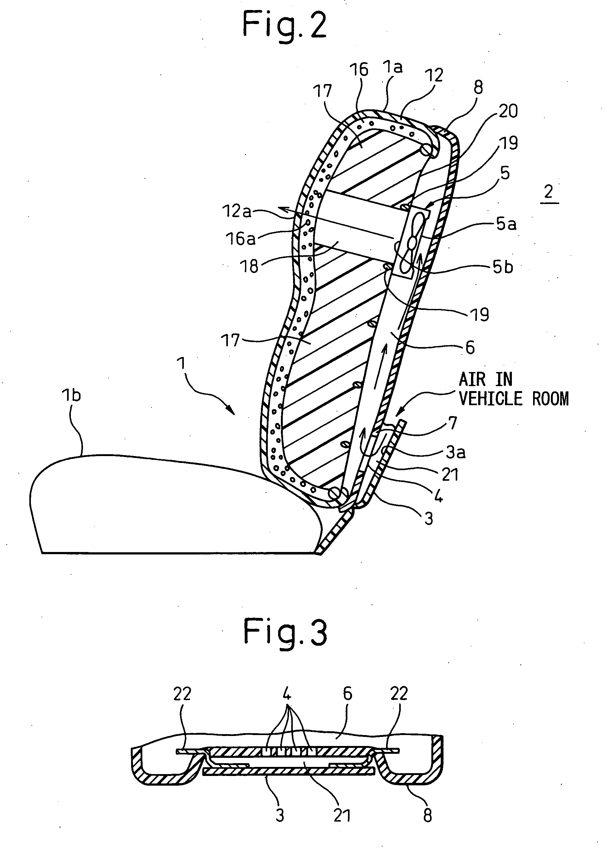
[0037] Referring to FIGS. 1 to 5, the first embodiment will be explained below. FIG. 1 is a rear view showing a structure of an air flow device incorporated into a seat of a vehicle of the present embodiment. FIG. 2 is a schematic sectional view showing the structure of the air flow device incorporated into a seat of a vehicle of the present embodiment. FIG. 3 is a schematic sectional illustration taken on line III-III in FIG. 1. FIG. 4 is a partial sectional view showing a relation between a suction port 4 and a pocket cover 3 in the air flow device incorporated into a seat of a vehicle of the present embodiment. FIG. 5 is a front view of a suction port 4 of the air flow device incorporated into a seat of a vehicle, wherein this view is taken from a reverse side of a pocket cover 3.

[0038] The air flow device incorporated into a seat of a vehicle of the present embodiment includes: a seat 1 of a vehicle including a seating portion 1b in which a passenger is seated and also includin...

Example

Second Embodiment

[0058] The air flow device incorporated into a seat for vehicle use of the second embodiment is different from the first embodiment in that the air flow device of the second embodiment includes a heat exchanger which is provided inside the seat and has a heat exchanging function so that the air in the vehicle passenger compartment 2 can be air-conditioned and blown out from the seat surface. The air flow device incorporated into a seat of a vehicle of the present embodiment will be explained by referring to FIGS. 6 to 8. FIG. 6 is a rear view showing a structure of an air flow device incorporated into a seat of a vehicle of the present embodiment. FIG. 7 is a schematic sectional illustration taken on line VII-VII in FIG. 6. FIG. 8 is a partial sectional view showing a relation between a suction port 4 and a filter 15 in the air flow device incorporated into a seat of a vehicle.

[0059] As shown in FIG. 6, the air flow device incorporated into a seat of a vehicle inc...

Example

Third Embodiment

[0074] The air flow device incorporated into a seat of a vehicle of the third embodiment is different from the first embodiment in that the suction port 11 is arranged at a position opposite to the reverse side of the seat handle cover 10. The air flow device incorporated into a seat of a vehicle of the third embodiment will be explained referring to FIGS. 9 and 10. FIG. 9 is a rear view showing a structure of the air flow device incorporated into a seat of a vehicle of the present embodiment, and FIG. 10 is a partial sectional view showing the relation between a suction port 11 and a seat handle cover 10 of the air flow device incorporated into a seat of a vehicle of the present embodiment.

[0075] As shown in FIG. 9, the air flow device incorporated into a seat of a vehicle includes: a seat handle cover 10 for covering both end portions of the handle 29; and a suction port 11, which is provided on the seat surface opposite to the reverse face of the seat handle cov...


PUM


Abstract

An air flow device incorporated into a seat of a vehicle comprises: a seat 1 of a vehicle including a seating portion 1b on which a passenger is seated and also including a seat back portion la against which passenger leans; a suction hole 4 open on a surface 7 of the seat of a vehicle, communicated with a vehicle passenger compartment 2; a suction air passage 6 formed inside the seat 1 of a vehicle, communicated with the suction hole 4; a blower 5 for forcibly generating an air current in the suction air passage 6; and a pocket cover 3 covering one portion of the surface of the seat 1 of a vehicle. Further, the suction hole 4 is arranged opposite to a reverse face 3a of the pocket cover. Due to the above constitution, it is possible to provide an air flow device, incorporated into a seat of a vehicle, which has a good appearance and an excellent air flow performance.

Description

BACKGROUND OF THE INVENTION [0001] 1. Field of the Invention [0002] The present invention relates to an air flow device incorporated into a seat of a vehicle which forces air from the vehicle passenger compartment through the seat. [0003] 2. Description of the Related Art [0004] Concerning this type air flow device incorporated into a seat of a vehicle, for example, the official gazettes of JP-A-2003-252036 and 2003-285628 disclose an air flow device in which an air current is blown out from a seat surface, into a vehicle passenger compartment, through an air passage formed in the seat. In this type air flow device incorporated into a seat of a vehicle, a flow of air is forcibly blown out into an air passage formed in the seat. The blast of air is blown out from a large number of small holes, which are formed on a seat surface communicated with the air passage formed in the seat, into the vehicle passenger compartment. [0005] In the air flow device incorporated into a seat of a vehi...

Claims


Application Information

Patent Timeline
IPC IPC(8): F25B21/02F25D23/12
CPCB60N2/5635B60N2/5657F25B21/02
Inventor ITO, YUJIAOKI, SHINJISAWAI, TAKUHIKO
Owner DENSO CORP
Why Eureka
Try Eureka