Microwave autoclave

a micro-wave and autoclave technology, applied in the field of autoclaves, can solve the problems of low general efficiency of heat transfer onto the surface via convection, inability to provide suitable wave-optical mirrors, and inability to uniformly heat up objects' surfaces

Inactive Publication Date: 2007-05-17
DEUTSCHES ZENTRUM FUER LUFT & RAUMFAHRT EV +1
View PDF7 Cites 14 Cited by
  • Summary
  • Abstract
  • Description
  • Claims
  • Application Information

AI Technical Summary

Problems solved by technology

Even the surfaces of the objects are not uniformly heated up by the hot air because, for example, of shadowing effects and other non-uniformities in the arrangement of the surfaces with regard to the hot air flow.
Further, the general efficiency in heat transfer onto the surfaces via convection is only low with the usual laminar air flows, as the flow velocity of the hot air goes down to zero in a boundary layer at the surfaces over which the air flows so that these boundary layers provide an unwanted thermal isolation layer about the respective object to be heated up.
In addition, the hot air in the pressure chamber of the autoclave not only heats up the objects to be treated but also the autoclave itself.
One obstacle for the practical application is that suitable wave-optical mirrors are not available.
Further, processing very large objects according to the known method using the known microwave system would require the application of very high power microwave sources.
Further, even with ideally homogenous field conditions of the applied microwave radiation, a homogenous temperature distribution over the objects to be treated could not be ensured because of different absorptions, reflections and shadowing of the microwave radiation within the processing volume already by the objects to be treated.
This construction has no stability in the range of higher pressures, as it is difficult to anchor the bodies of dielectric material in the pressure resistant wall in a pressure tight and pressure resistant way.
Further, it does not seem to be realistic that a stationary microwave having nodes at the pressure resistant wall can be formed in the pressure chamber independently of the objects loaded into the pressure container having a fixed diameter.
It does also not seem to be realistic that, upon constructing the pressure chamber as a cavity resonator for the microwave, a homogenous distribution of the microwave intensity over the pressure chamber is actually achieved.

Method used


Image

  • Microwave autoclave
  • Microwave autoclave
  • Microwave autoclave

Examples


Embodiment Construction

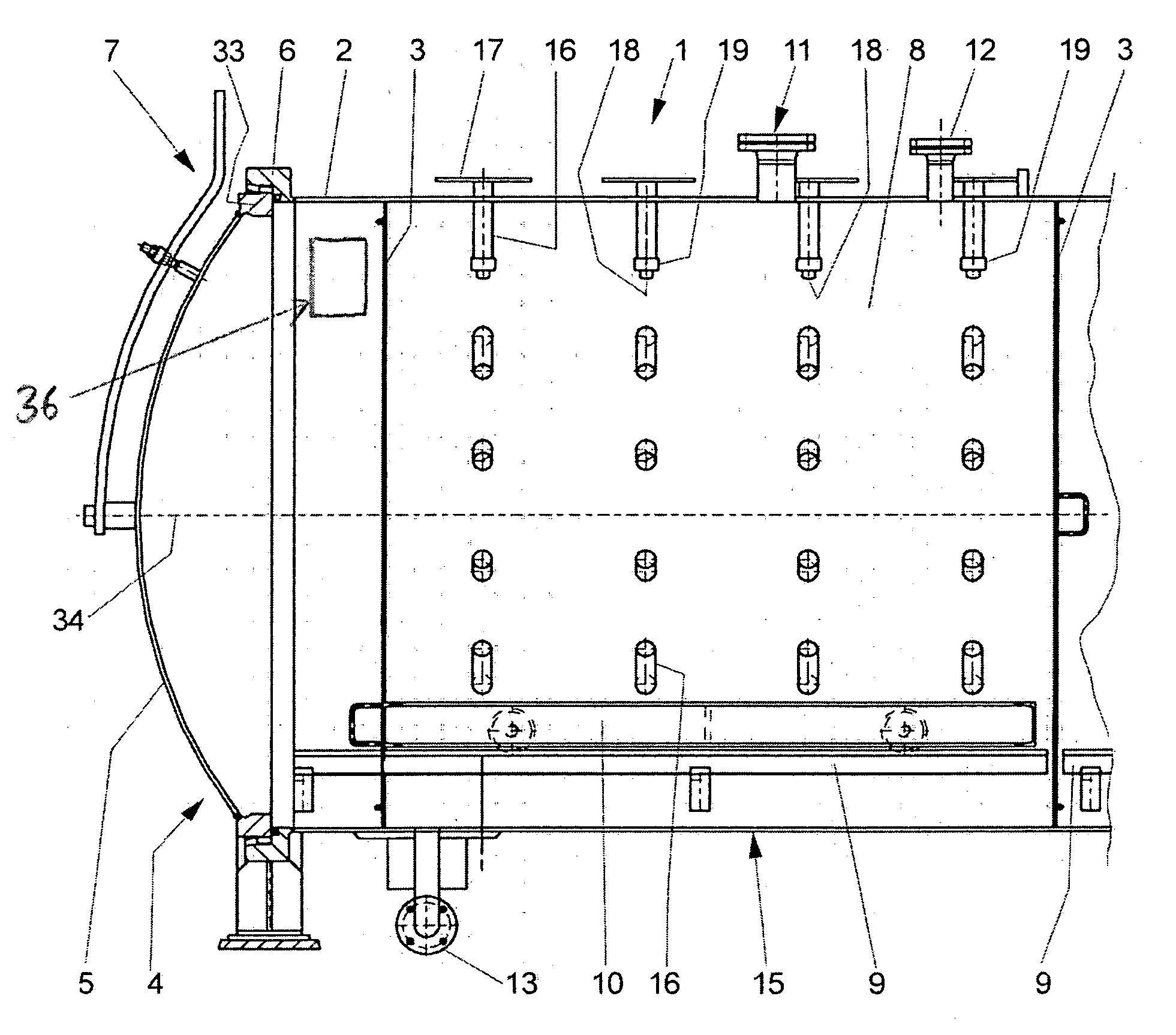
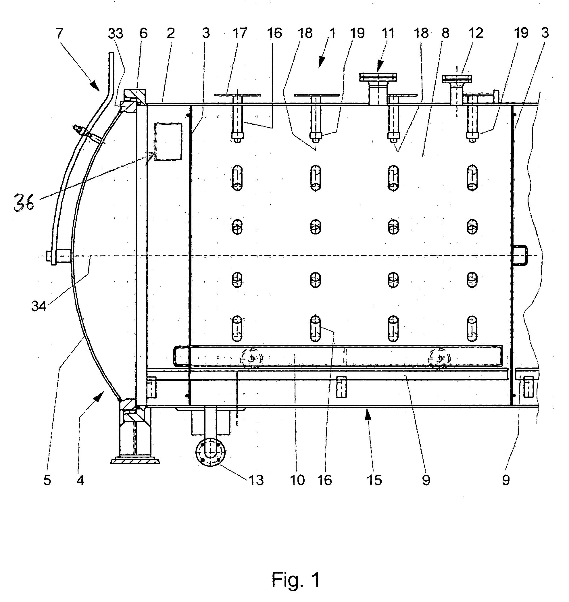
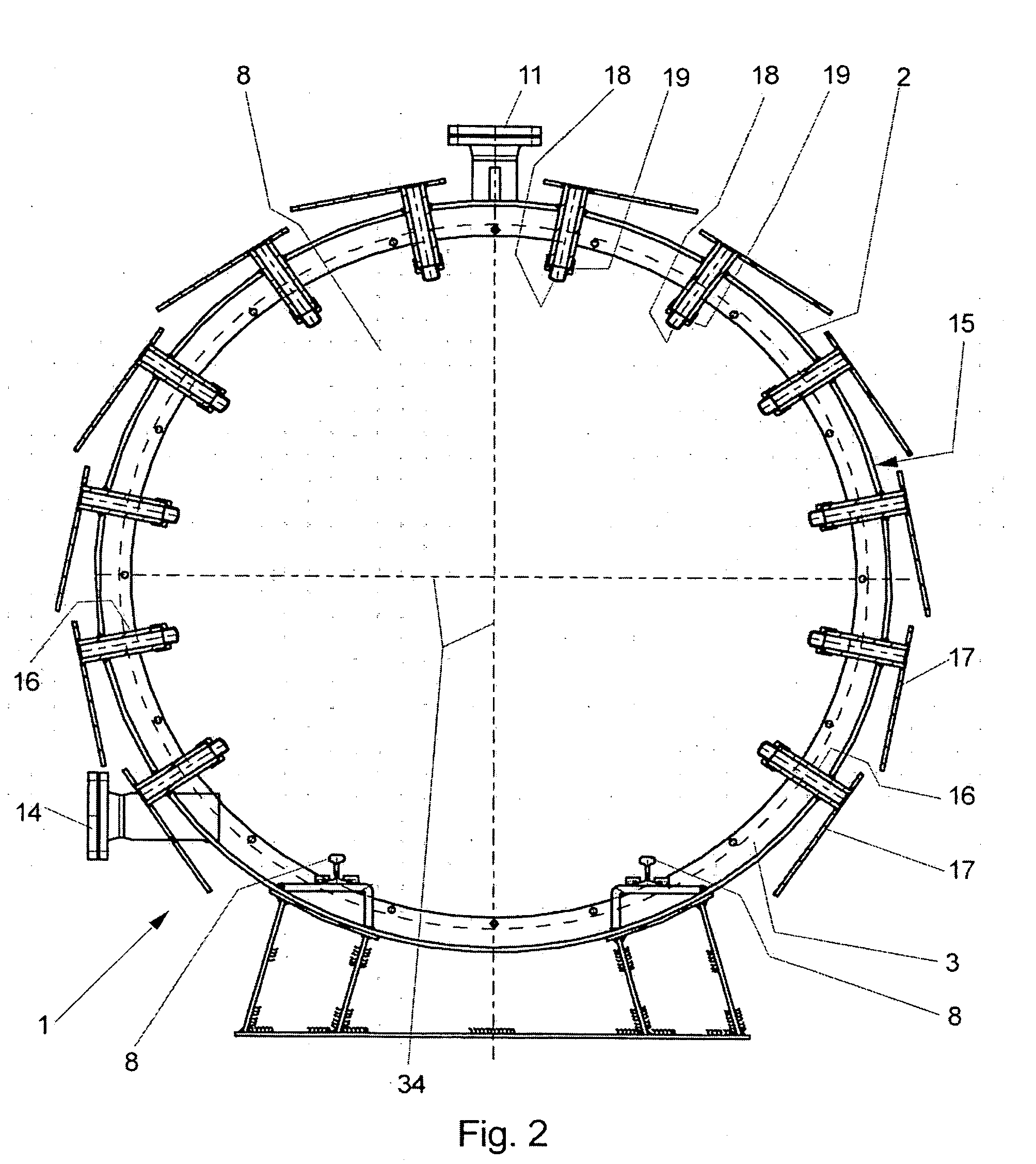
[0018] In the new autoclave the heat source for heating the objects arranged in the pressure chamber has a plurality of microwave sources. Because of this, the new autoclave is also designated as a microwave autoclave here. The new microwave autoclave combines the thermal treatment of objects using microwave radiation for heating the objects with a simultaneous pressure treatment of the objects. The microwave radiation irradiated by the microwave sources is coupled into the pressure chamber to act upon, i.e. to heat up the objects arranged in the pressure chamber.

[0019] In the new microwave autoclave at least four microwave source per square meter surface area of the pressure resistant wall are provided to achieve a homogeneous temperature distribution over the objects arranged in the pressure chamber. This figure is based on an industrial scale autoclave having an outer diameter of at least about 2 m and a free inner diameter of the pressure chamber of at least about 1.5 m as well...


PUM

PropertyMeasurementUnit
inner diameteraaaaaaaaaa
frequencyaaaaaaaaaa
frequenciesaaaaaaaaaa

Abstract

An autoclave for pressure and temperature treatment of objects comprises a pressure container having a pressure resistant wall which encloses a pressure chamber for receiving the objects to be treated, said pressure chamber having a free inner diameter of at least 1.5 m; and a heat source for heating the objects received in said pressure chamber, said heat source including a plurality of microwave sources irradiating microwave radiation, which are arranged outside said pressure container. Said microwave sources are distributed over said pressure resistant wall at an areal density of at least 4 microwave sources per square meter surface area of said pressure resistant wall; and the microwave radiation irradiated by said microwave sources is coupled through said pressure resistant wall into said pressure chamber.

Description

CROSS REFERENCE TO RELATED APPLICATIONS [0001] This application claims priority to co-pending German Patent Application No. DE 10 2005 050 528.7 entitled “Mikrowellenautoklav”, filed Oct. 21, 2005. FIELD OF THE INVENTION [0002] The present invention relates to an autoclave for pressure and temperature treatment of objects. Particularly, the present invention relates to an autoclave for the manufacture of fiber compound parts. [0003] There are various objects which are purposefully treated by pressure and temperature in an autoclave. These objects inter alia include foodstuffs which are sterilized in such an autoclave, and building materials, like for example lime sand bricks which are cured in an autoclave. In the following description it will be particularly referred to a further example of applying an autoclave, i. e. the manufacture of large size fiber compound parts made of fiber enforced plastics, like for example carbon fiber enforced or glass fiber enforced plastics. Such lar...

Claims


Application Information

Patent Timeline
Patent Type & Authority Applications(United States)
IPC IPC(8): H05B6/70
CPCB01J3/03B01J19/126B01J2219/0879H05B6/72H05B6/80H05B2206/044
Inventor MEYER, MATTHIASBINDER, BURKHARDGRAEBER, MARTIN
Owner DEUTSCHES ZENTRUM FUER LUFT & RAUMFAHRT EV
Why Eureka
Try Eureka