Spring core

a spring core and core technology, applied in the field of spring cores, can solve the problems of multiple unfavorable effects, high transportation costs from the manufacturer of the spring core to the further processing company, and the electrical conductivity of the helical spring consisting of metal, and achieve the effect of short formation

Inactive Publication Date: 2007-05-17
AGRO FEDERKERNPRODN
View PDF11 Cites 85 Cited by
  • Summary
  • Abstract
  • Description
  • Claims
  • Application Information

AI Technical Summary

Benefits of technology

[0019] It is advantageous to keep the spring band, which is bent to form at least a partial ring, prestressed by a ten...

Problems solved by technology

Thus, the relatively high weight of the spring cores equipped with metal springs has multiple unfavorable effects.
For example, as a result of the high weight, the transport costs from the manufacturer of the spring cores to the further processing company are relatively high, which naturally stands in the way of an optimized cost structure.
Another disadvantageous criterion is the electrical conductivity of the helical spri...

Method used


Image

  • Spring core
  • Spring core
  • Spring core

Examples


Embodiment Construction

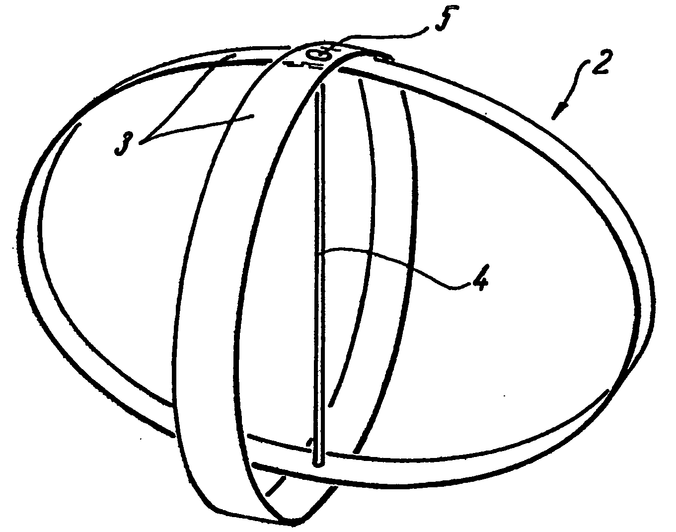
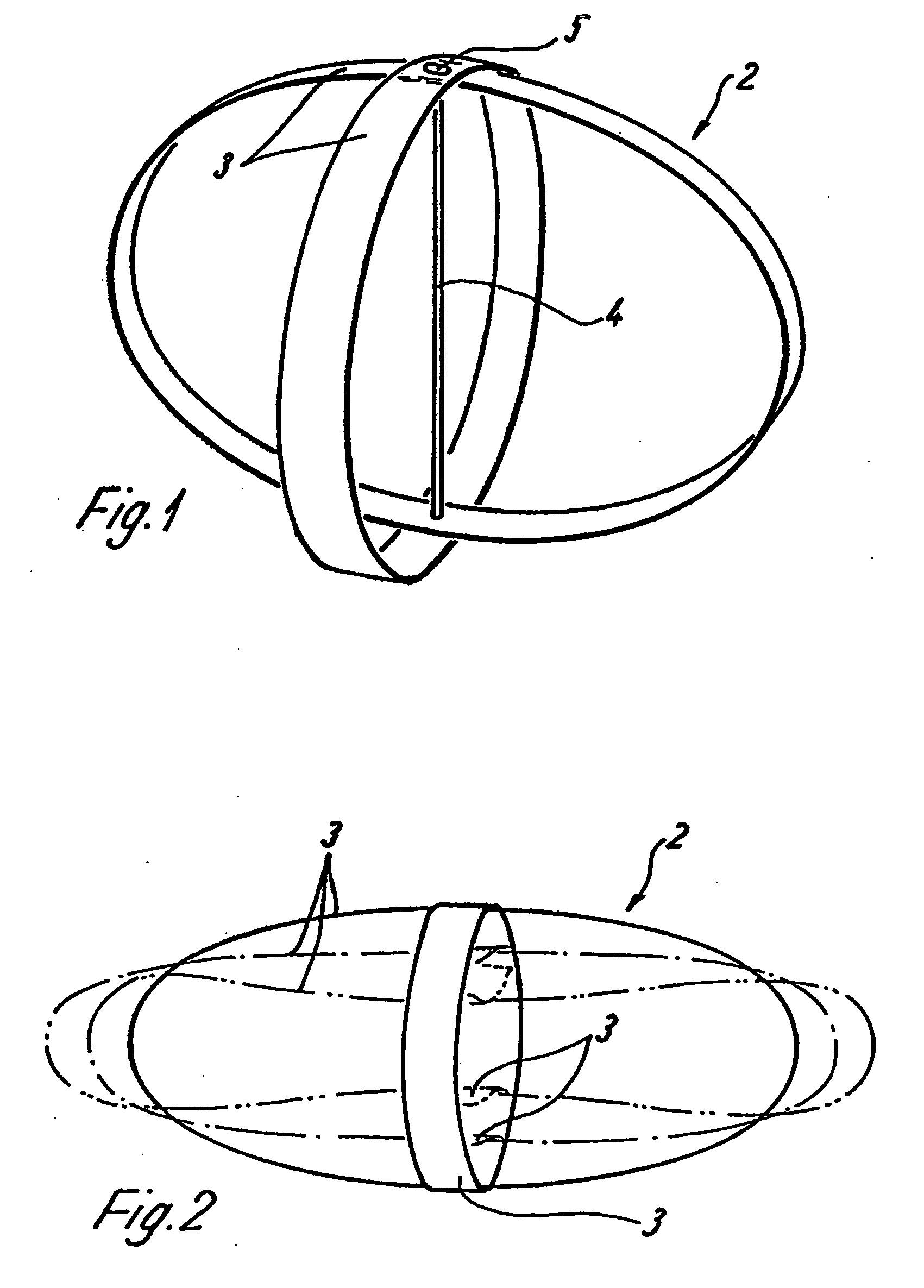
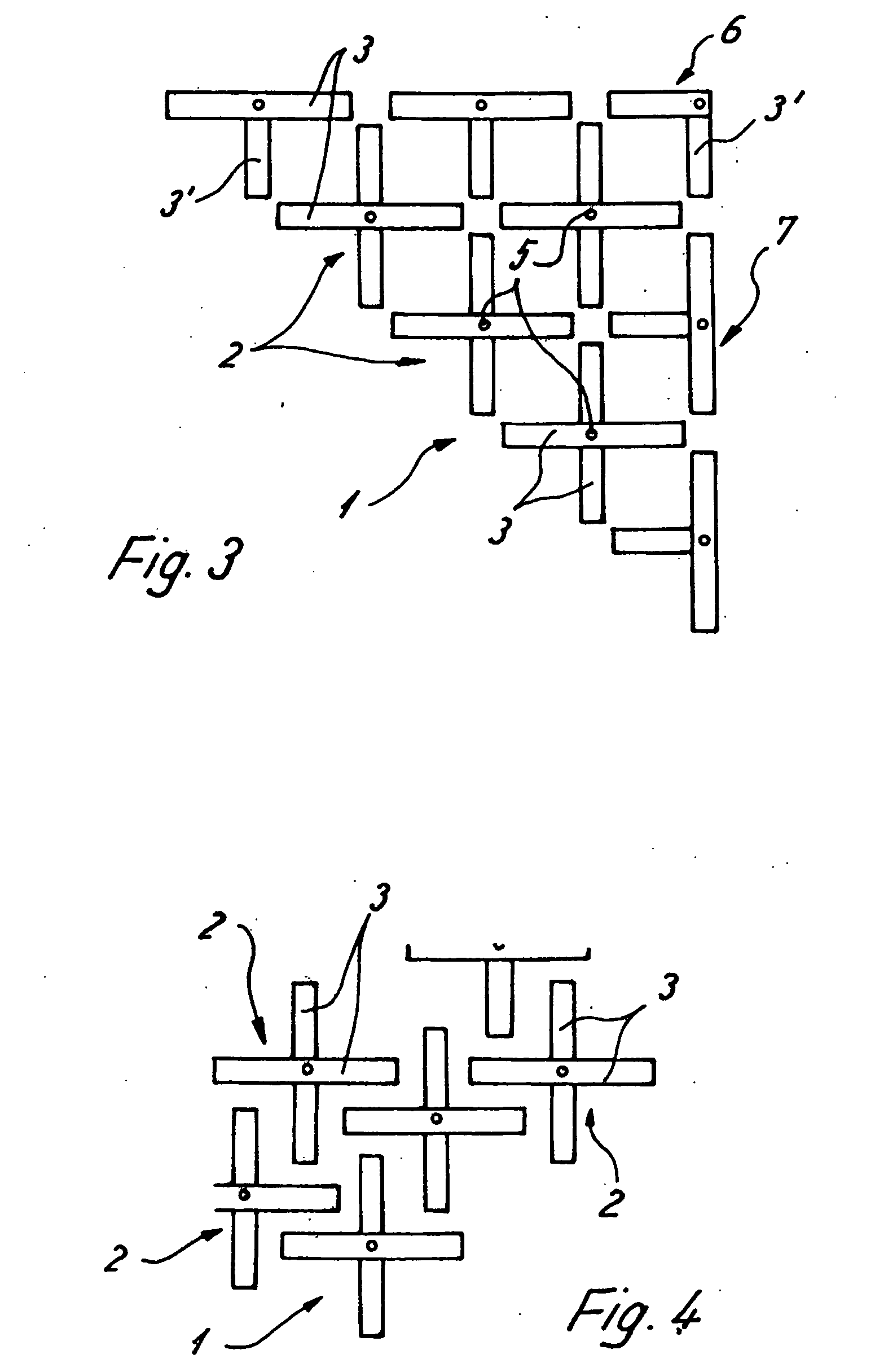
[0028] Embodiments of a spring core 1 are shown in FIGS. 3 and 4 as partial cutouts. Spring cores 1 include a plurality of individual springs 2 which are each formed of at least one spring band 3 deformable in a bulge-type fashion when loaded. Individual springs 2 are shaped in a loading plane to form at least a partial ring, as shown in FIGS. 1 and 2. The solid lines in FIG. 2 indicate an unloaded position of the individual spring 2, while different loading positions are illustrated by dash-dotted lines in FIG. 3, in which the individual springs 2 are compressed to a corresponding degree.

[0029] An outer border of the spring core 1 is bounded by border springs 7 (see FIG. 3) as well as by a corner spring 6 at each corner. Border spring 7 includes a fully circumferential spring band 3, which forms a closed ring. Also included is a half a ring 3′, which extends in an interior direction of the spring core 1, while the spring band 3 formed as a closed ring forms an outer edge.

[0030] T...


PUM


Abstract

A spring core includes a plurality of individual springs. Each individual spring includes at least one spring band configured to be deformed to have a bulge and shaped to form at least a partial ring in a loading plane.

Description

BACKGROUND AND SUMMARY CROSS-REFERENCE [0001] This application claims priority to German Application 10 2005 054 725.7 filed Nov. 17, 2005, which disclosure is hereby incorporated herein by reference. BACKGROUND AND SUMMARY [0002] The present disclosure relates to a spring core including a plurality of individual springs. [0003] Such spring cores are used in different fields. As an example, spring cores are used for upholstered furniture, particularly for mattresses. [0004] The individual springs of the known spring cores are constructed as helical springs and normally consist of metal. [0005] However, the known spring cores have a number of disadvantages. Thus, the relatively high weight of the spring cores equipped with metal springs has multiple unfavorable effects. For example, as a result of the high weight, the transport costs from the manufacturer of the spring cores to the further processing company are relatively high, which naturally stands in the way of an optimized cost ...

Claims


Application Information

Patent Timeline
IPC IPC(8): F16F1/18
CPCA47C27/062A47C27/065
Inventor GROTHAUS, WOLFGANG
Owner AGRO FEDERKERNPRODN
Why Eureka
Try Eureka