Liquid hand wash container

a handwashing container and liquid technology, applied in the direction of dispensers, holders, single-unit apparatuses, etc., can solve the problems of high cost, easy damage, inconvenient operation, etc., and achieve the effect of small press force, reliable structure and short formation

Active Publication Date: 2019-11-19
XIE HUOXIAN
View PDF8 Cites 0 Cited by
  • Summary
  • Abstract
  • Description
  • Claims
  • Application Information

AI Technical Summary

Benefits of technology

[0004]An object of the present invention is to provide a liquid hand wash container which is small in press force and easy to be operated, so as to solve technical problems of existing press-type liquid hand wash container such as inconvenient operation, large press force and long press stroke. Specific technical solutions of the present invention are as follows.
[0015]Compared with the prior art, the liquid hand wash container provided by the present invention has main beneficially effects as follows. Each of the thrust arc plates of the present invention has a concave arc-shaped end which presses against the compression rod module to drive the compression rod module to move, so as to further drive the pressing base to move upwardly; the liquid discharging nozzle is connected with the pressing base for discharging the liquid; a geometric shape of each of the thrust arc plates is based on the vector analysis of the thrust arc plates on the compression rod module during the entire press process, so that the entire press process is short in formation and small in press force. Moreover, the present invention is reliable in structure and low in manufacturing cost.

Problems solved by technology

However, the liquid is commonly discharged in existing liquid hand wash containers through pressing the pressing plate with springs, which requires people to use greater power during operation, and is long in press stroke, inconvenient to operate, difficult for people with disabilities to use, easy to be damaged and high in cost.

Method used


Image

  • Liquid hand wash container
  • Liquid hand wash container
  • Liquid hand wash container

Examples


embodiment

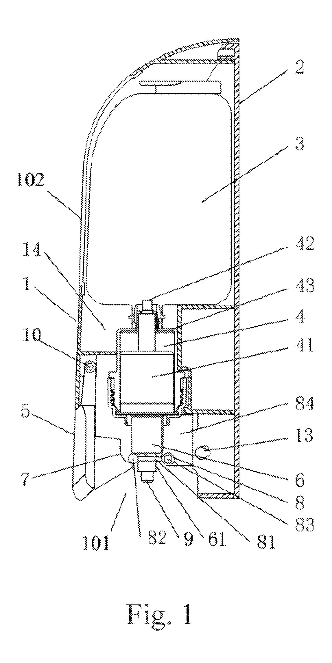
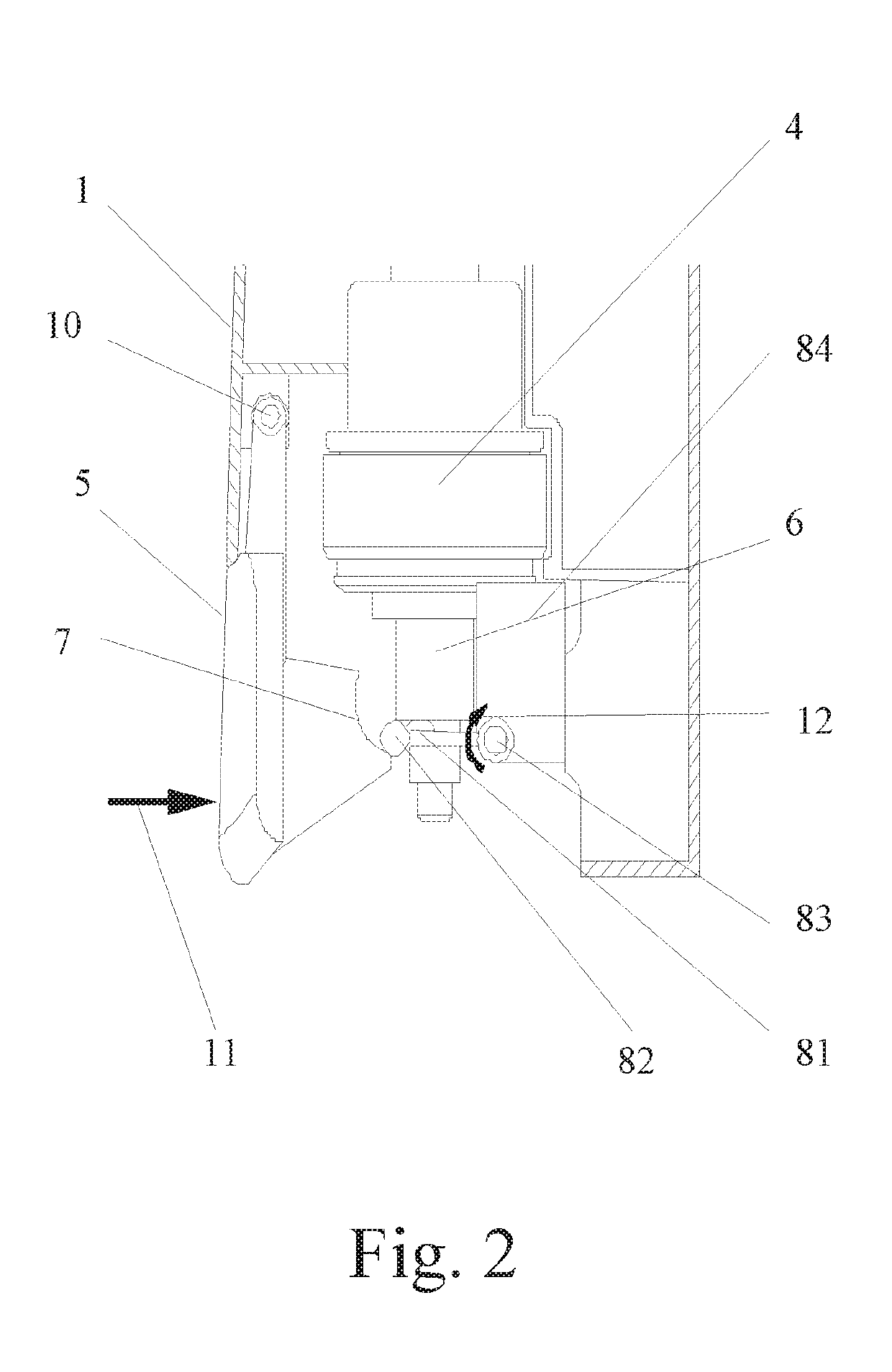
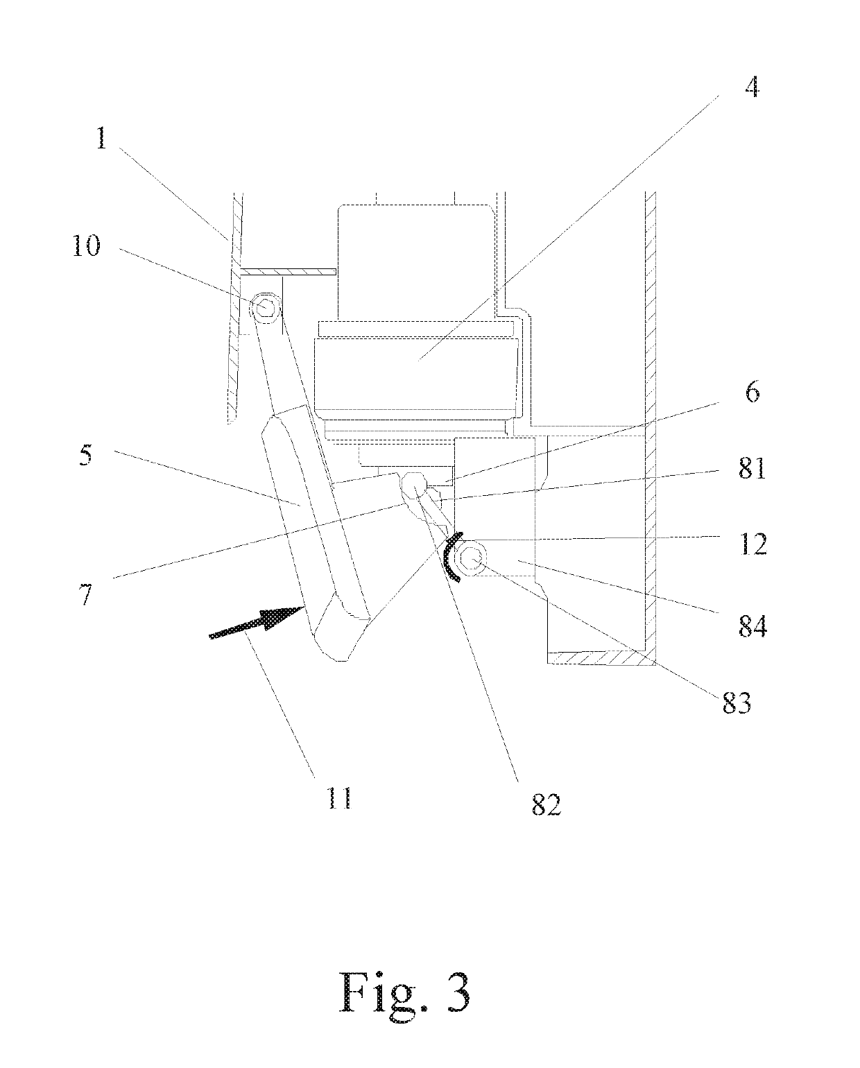
[0020]Referring to FIG. 1, a liquid hand wash container is illustrated, which comprises an outer casing 1, a rear casing 2, a liquid storage bottle 3, a liquid discharging pump module 4, a pressing plate 5, a pressing base 6, two thrust arc plates 7 and a compression rod module 8, wherein the liquid discharging pump module 4 comprises a liquid discharging pump 41 and a liquid discharging tube 42; the outer casing 1 and the rear casing 2 are connected with each other to form an accommodating cavity 14 through a buckle 13; all of the liquid storage bottle 3, the liquid discharging pump module 4, the pressing base 6 and the compression rod module 8 are disposed within the accommodating cavity 14; all of the liquid storage bottle 3, the liquid discharging pump module 4 and the compression rod module 8 are fixedly disposed on the rear casing 2; an upper portion of the liquid discharging pump 41 is connected with the liquid storage bottle 3 through the liquid discharging tube 42, a lower ...


PUM


Abstract

A liquid hand wash container includes an outer casing, a rear casing, a liquid storage bottle, a liquid discharging pump module, a pressing plate, a pressing base, two thrust arc plates and a compression rod module, wherein the outer housing and the rear housing are connected with each other to form an accommodating cavity through a buckle; all of the liquid storage bottle, the liquid discharging pump module, the pressing base (6) and the compression rod module (8) are disposed within the accommodating cavity; all of the liquid storage bottle (3), the liquid discharging pump module and the compression rod module are fixedly disposed on the rear housing; an upper portion of a liquid discharging pump is connected with the liquid storage bottle through a liquid discharging tube, a lower portion of the liquid discharging pump is movably connected with the pressing base.

Description

CROSS REFERENCE OF RELATED APPLICATION[0001]This is a U.S. National Stage under 35 U.S.C 371 of the International Application PCT / CN2016 / 089242, filed Jul. 7, 2016, which claims priority under 35 U.S.C. 119(a-d) to CN 201510394195.7, filed Jul. 7, 2015.BACKGROUND OF THE PRESENT INVENTIONField of Invention[0002]The present invention relates to a disinfecting and cleaning device, and more particularly to a liquid hand wash container.Description of Related Arts[0003]With the increase of living standards, people pay more and more attention to sanitation supplies. Now, disinfectant and liquid hand wash have been widely used in toilets and other places. Generally, the disinfectant and the liquid hand wash are firstly bottled and then installed into a liquid discharging container, and the liquid is discharged through manually pressing the pressing plate. However, the liquid is commonly discharged in existing liquid hand wash containers through pressing the pressing plate with springs, whic...

Claims


Application Information

Patent Timeline
Patent Type & Authority Patents(United States)
IPC IPC(8): B05B11/00A47K5/12
CPCB05B11/3014A47K5/1207B05B11/3057B05B11/1057A47K5/12B05B11/00B05B11/1014
Inventor YAU, KAM KINGXIE, HUOXIAN
Owner XIE HUOXIAN
Why Eureka
Try Eureka