Contact device for cone ring transmission

A technology of pressing device and transmission, applied in the direction of transmission, friction transmission, transmission control, etc., can solve problems such as interruption of torque flow and damage

Inactive Publication Date: 2008-02-27
GETRAG FORD TRANSMISSIONS GMBH
View PDF1 Cites 6 Cited by
  • Summary
  • Abstract
  • Description
  • Claims
  • Application Information

AI Technical Summary

Problems solved by technology

However, the hold-down device of DE 103 48 718 A1 has the disadvantage that in an emergency a sufficient pressure must be available for the hydraulic hold-down unit
But if the system used to supply this pressure in an emergency is also compromised, the torque flow in the cone ring transmission is no longer interrupted as required

Method used


Image

  • Contact device for cone ring transmission
  • Contact device for cone ring transmission

Examples


Embodiment Construction

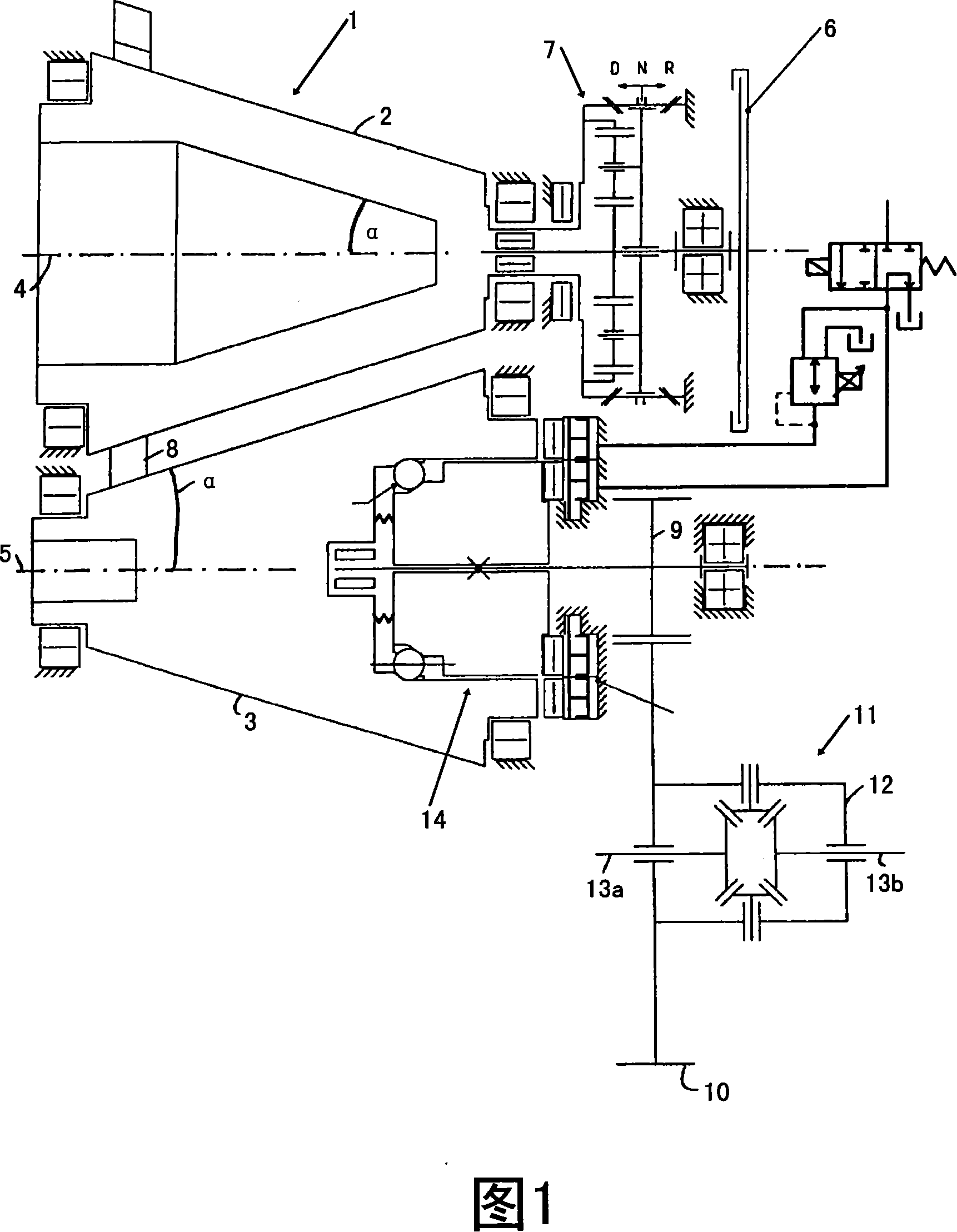
[0022] FIG. 1 shows a cone ring transmission, which is generally designated 1 . The bevel ring transmission 1 has a first conical friction wheel 2 and a second conical friction wheel 3 . The conical friction wheels 2 , 3 are arranged opposite one another, with their axes of rotation extending parallel and spaced apart from one another. The axes of rotation of the conical friction wheels 2 , 3 are indicated by dashed lines 4 , 5 . Each conical friction wheel 2, 3 has an opening angle α.

[0023] In addition to the cone ring transmission 1 , FIG. 1 also shows a clutch 6 of the motor vehicle, which is not further shown here. A front transmission 7 is connected between the first conical friction wheel 2 and the clutch 6 . The front drive 7 in the form of a planetary gear train can switch between the two driving directions of the motor vehicle (forward, backward). In the engaged state, the clutch 6 transmits the torque of a drive device or a motor (not shown) to the first conic...


PUM


Abstract

The present invention relates to a pressing device (14) used for the conical ring speed changer (1), the speed changer includes two cone friction wheels (2, 3) and a friction ring (8) arranged between the two cone friction wheels (2, 3), the pressing device is provided with a mechanical pressing unit (15) and a hydraulic pressing unit (16), wherein the mechanical pressing unit (15) exerts one pressing force to at least one cone friction wheel (3) in order to cause the cone friction wheels (2, 3) impacting with each other at the condition that the friction ring (8) is used, the device is characterized in that the mechanical pressing unit (15) does not exert pressing force or obvious-diminished pressing force when the hydraulic pressing unit (16) is in the non-pressure position.

Description

technical field [0001] The invention relates to a pressing device for a cone ring transmission, which comprises two conical friction wheels and a friction ring arranged between the two conical friction wheels. Background technique [0002] DE 103 48 718 A1 discloses a pressing device for a bevel ring transmission, which has a mechanical pressing unit and a hydraulic pressing unit. A mechanical pressing unit, which also has a spring element, exerts a pressing force on one of the conical friction wheels, so that the conical friction wheels can be pressed against each other when a friction ring is used. Through this pressing, torque can be transmitted from one friction cone to the other friction cone via the friction ring. [0003] The mechanical hold-down unit is supported on the one hand on a bearing that absorbs the axial force and on the other hand on one of the conical friction wheels. In this case, the mechanical pressing unit exerts a pressure by which the conical fric...

Claims


Application Information

Patent Timeline
Patent Type & Authority Applications(China)
IPC IPC(8): F16H15/42
CPCF16H61/6649F16H37/021F16H15/42
Inventor S·邦加特J-P·沙佐特R·菲肯斯S·科库斯G·威尔施
Owner GETRAG FORD TRANSMISSIONS GMBH
Why Eureka
Try Eureka