Method and apparatus for defect correction in a display

a technology for defect correction and display, applied in the field of displays, can solve the problems of display defect correction, display defect correction, display defect correction, etc., and achieve the effects of improving manufacturing yield, improving power efficiency, and improving uniformity and quality

Active Publication Date: 2007-05-17
GLOBAL OLED TECH
View PDF4 Cites 51 Cited by
  • Summary
  • Abstract
  • Description
  • Claims
  • Application Information

AI Technical Summary

Problems solved by technology

In general, displays suffer from a variety of defects that limit their quality.
In particular, displays may suffer from defective light-emitting elements that do not respond properly to control signals, for example, the defective light-emitting elements may be permanently turned on, permanently turned off, be brighter, and / or be dimmer than intended for a given control signal.
These non-uniformities can be attributed to the light-emitting or light-controlling materials in the display or, for active-matrix displays, to variability in the thin-film transistors used to drive the light emitting elements.
Furthermore, most displays are color displays having pixels with three or four colored light-emitting elements and defects may be found in one color light-emitting element of a display pixel but not in the other color light-emitting elements of the same pixel.
Such defects reduce the quality, reduce the manufacturing yields, and increase the costs of flat-panel displays.
However, such uniformity correction schemes may not sufficiently correct for display devices having defective light-emitting elements that are stuck on or stuck off, or that are not sufficiently responsive to control signals to perform the desired correction.
However, such an approach often creates visible spatial artifacts because of the distance between the sub-pixels of a common color.
However, there is no teaching with respect to optimal correction for defective pixels in systems in which combinations of sub-pixels can generate a color found in an other sub-pixel, for example as taught in U.S. Pat. No. 6,919,681 referenced above.
However, in this design, the spatial extent of the corrected light-emitting elements is not optimized, and is thus more visible than may be necessary.

Method used


Image

  • Method and apparatus for defect correction in a display
  • Method and apparatus for defect correction in a display
  • Method and apparatus for defect correction in a display

Examples


Embodiment Construction

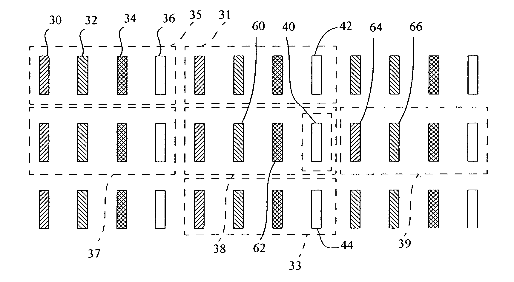
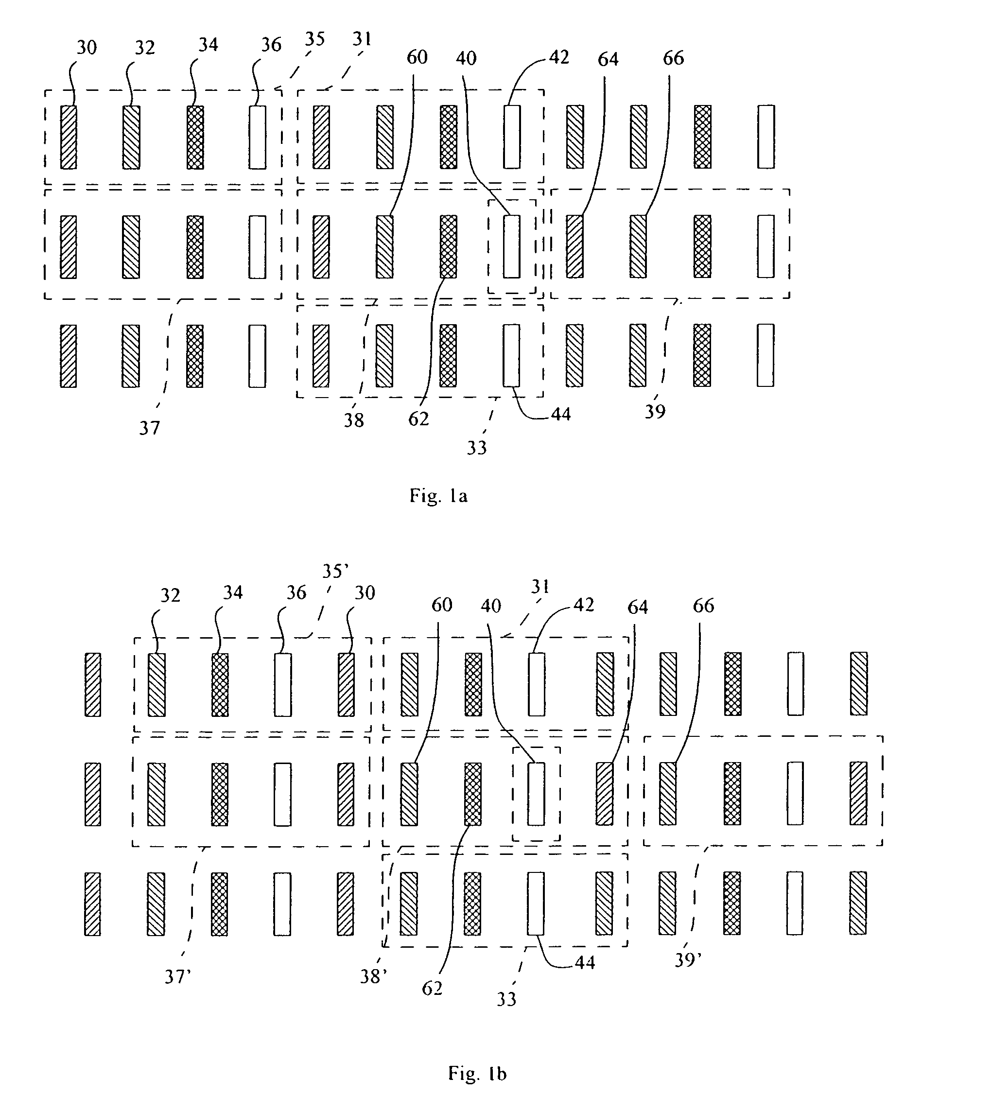
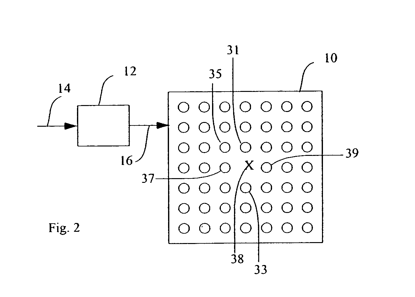
[0018] Referring to FIG. 1a, in an embodiment of the present invention, a full-color display device comprises a display having a plurality of sub-pixels (e.g., 30, 32, 34, 36, 40, 42, 44, 60, 62, 64, and 66) formed in rows in a first dimension and grouped into pixels (e.g., 31, 33, 35, 37, 38, and 39) within each row, each pixel including at least three color sub-pixels (e.g. red 30, 64, green 32, 60, and blue 34, 62) forming a color gamut and at least one additional sub-pixel (e.g. 36, 40, 42, 44) having a color within the gamut and an efficiency higher than at least one of the color sub-pixels wherein at least one pixel (e.g., 38) is defective and comprises one defective additional in-gamut sub-pixel (e.g., 40). Referring to FIG. 2, a controller 12 for driving the display 10 pixels and for transforming an input signal 14 into a compensated signal 16 for selectively modifying the output of at least one color sub-pixel in the defective pixel 38, at least one other, but not all, of t...


PUM


Abstract

A full-color display device, comprising: a) a display having a plurality of sub-pixels formed in rows or columns in a first dimension including at least three different color sub-pixels forming a color gamut, and grouped into pixels within each row or column, each pixel including at least two of the gamut-specifying color sub-pixels and at least one additional sub-pixel having a color within the gamut and an efficiency higher than at least one of the color sub-pixels, wherein at least one pixel is defective and comprises one defective additional in-gamut sub-pixel; and b) a controller for driving the display pixels and for transforming an input signal into a compensated signal for selectively modifying the output of at least one color sub-pixel in the defective pixel, at least one other, but not all, of the color sub-pixels in a neighboring pixel in the first dimension, and additional in-gamut sub-pixels in neighboring pixels in a second dimension, the at least one other color sub-pixel including the sub-pixel in the neighboring pixel that is closest to the defective sub-pixel, to compensate for the output of the defective sub-pixel(s).

Description

FIELD OF THE INVENTION [0001] The present invention relates to displays having a plurality of colored light-emitting elements and, more particularly, correcting for defective light-emitting elements in the display. BACKGROUND OF THE INVENTION [0002] Flat-panel display devices, for example plasma, liquid crystal and Organic Light Emitting Diode (OLED) displays have been known for some years and are widely used in electronic devices to display information and images. Such devices employ both active-matrix and passive-matrix control schemes and can employ a plurality of colored light-emitting elements to form a full-color, pixilated display. Each pixel comprises a plurality of colored sub-pixel light-emitting elements, for example red, green, and blue. It is also known to provide color displays with four colored sub-pixels in each pixel of a full-color display to reduce power usage, for example as taught in U.S. Pat. No. 6,919,681 by Cok et al. The light-emitting elements are typically...

Claims


Application Information

Patent Timeline
Patent Type & Authority Applications(United States)
IPC IPC(8): G09G5/10
CPCG09G3/2003G09G2300/0452G09G2320/0233G09G2320/0242G09G2330/08
Inventor COK, RONALD S.KANE, PAUL J.
Owner GLOBAL OLED TECH
Why Eureka
Try Eureka