Structure of three-dimensional image data, method of recording three-dimensional image data, and method of displaying and reproducing three-dimensional image data

a three-dimensional image data and image data technology, applied in the field of three-dimensional image data structure, can solve the problems of complex image formats, difficult to implement image pickup apparatuses, and one-dimensional ip schemes that require complex image formats

Inactive Publication Date: 2007-05-17
KK TOSHIBA
View PDF11 Cites 14 Cited by
  • Summary
  • Abstract
  • Description
  • Claims
  • Application Information

AI Technical Summary

Benefits of technology

[0019] providing data on n or more parallax component images in each of which pixel columns allowing the pixels to generate parallel rays in the same parallax direction in the viewing area are accumulated, the parallax component images having different numbers of horizontal pixels, and
[0020] recording the data by c

Problems solved by technology

It is difficult to implement an image pickup apparatus that varies the projection method or a projection center distance between the vertical direction and the horizontal direction.
However, the parallel-ray one-dimensional IP scheme requires complex image formats for the projection method and the dividing and arranging method.
With the parallel-ray one-dimensional IP scheme, the number of horizontal pixels (horizontal range used to display three-dimensional images) in each parallax component image varies depending on parallax direction, resulting in complex image formats.
Both the multiview scheme and parallel-ray one-dimensional IP scheme pose a problem if each piece of parallax information is divided into subpixels assigned to a parallax synthetic image.
When a parallax synthetic image is irreversibly compressed by an encoding method such as JP

Method used


Image

  • Structure of three-dimensional image data, method of recording three-dimensional image data, and method of displaying and reproducing three-dimensional image data
  • Structure of three-dimensional image data, method of recording three-dimensional image data, and method of displaying and reproducing three-dimensional image data
  • Structure of three-dimensional image data, method of recording three-dimensional image data, and method of displaying and reproducing three-dimensional image data

Examples


Embodiment Construction

[0063] With reference to the drawings, description will be given of methods of recording and reproducing a three-dimensional display image in accordance with an embodiment of the present invention.

[0064] First, with reference to FIGS. 1 to 11, description will be given of a display apparatus and method in accordance with the IP scheme.

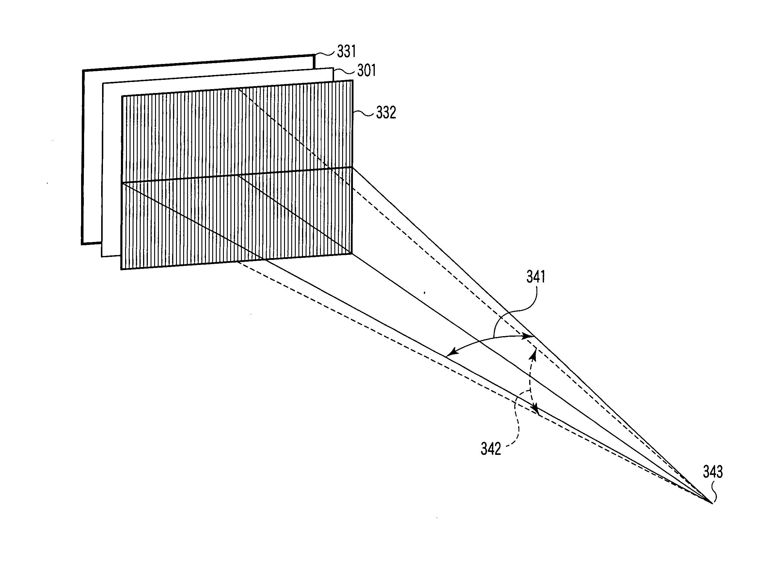
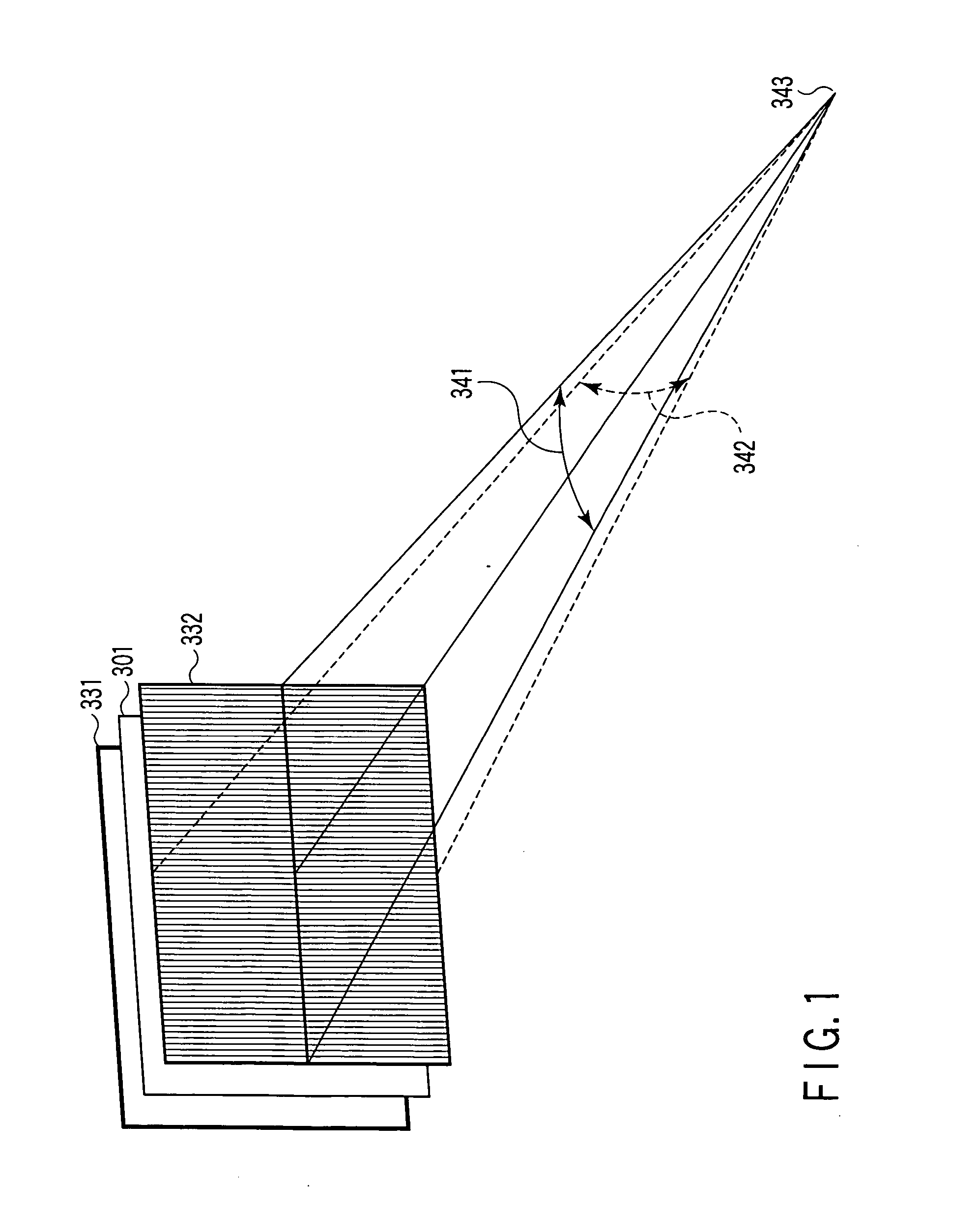
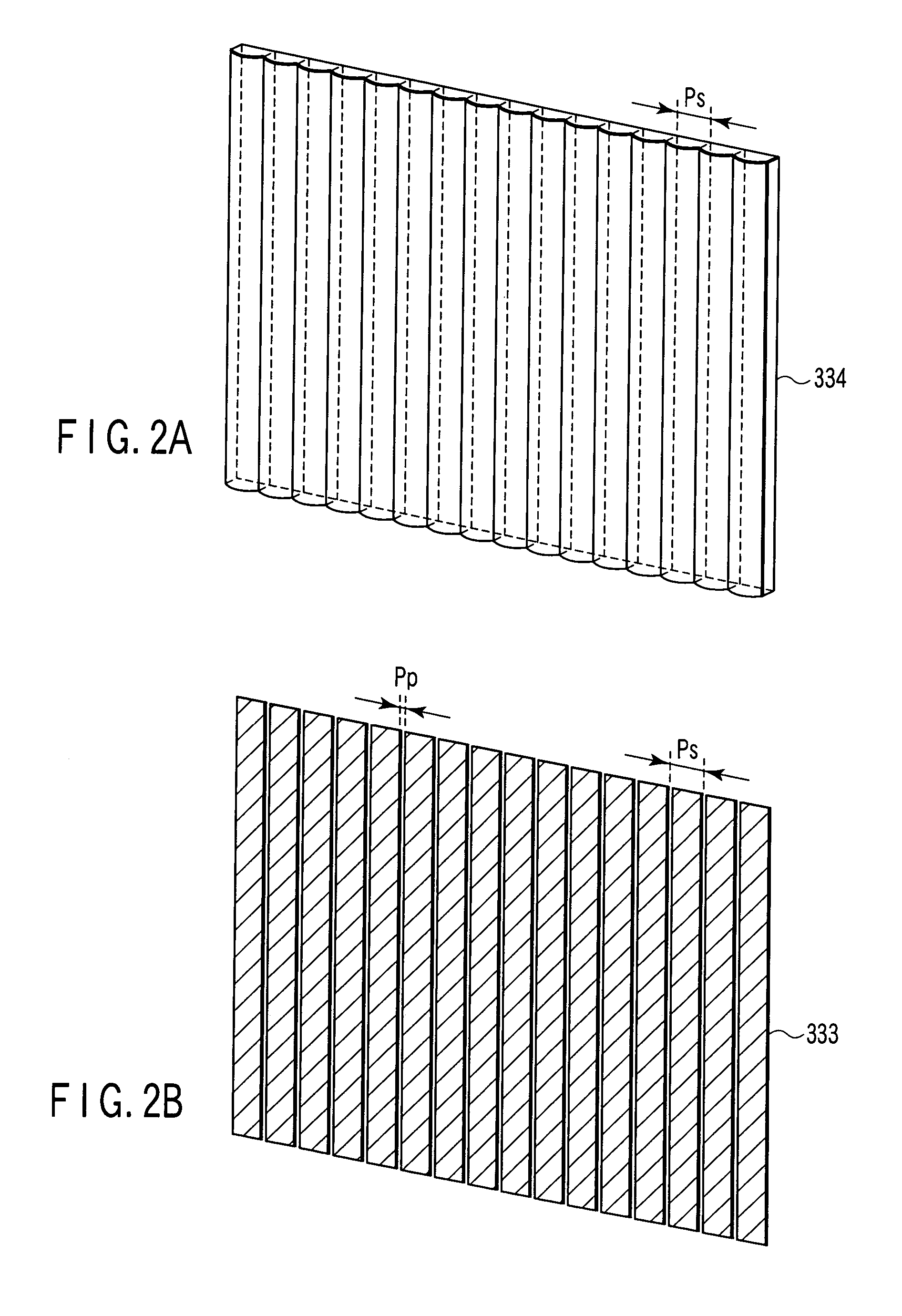
[0065]FIG. 1 is a perspective view schematically showing an entire three-dimensional image display apparatus. The display apparatus displaying a three-dimensional image shown in FIG. 1 comprises a planar display section 331 that displays a parallax synthetic image (elemental image array) as a planar image. A lenticular sheet 334 shown in FIG. 2A or a slit array plate 333 shown in FIG. 2B is placed in front of the planar display section 331 as a parallax barrier 332 that controls rays from the display section 331. Here, the lenticular lens 334 or the slit array plate 333 is collectively referred to as a parallax barrier 332. The parallax barrier compr...


PUM


Abstract

An apparatus displaying a three-dimensional image is provided with a parallax barrier having optical openings arranged at a horizontal pitch n times as large as that of pixels arranged on a display surface. The parallax barrier reproduces rays from every n pixels on the display surface in a horizontal direction and no vertical parallaxes is displayed in a viewing area. Image data for a three-dimensional image is processed so as to be recorded in an efficient saving format which minimizes the degradation of image quality while accomplishing a high compression rate. Image data from a set of pixels constituting parallel rays in the same parallax direction are accumulated to obtain more than n parallax component images. Parallax component images corresponding to n-th adjacent parallax directions are combined together and thus converted into n connected images having the same numbers of vertical and horizontal pixels.

Description

CROSS-REFERENCE TO RELATED APPLICATIONS [0001] This is a Continuation Application of PCT Application No. PCT / JP2005 / 017978, filed Sep. 29, 2005, which was published under PCT Article 21(2) in Japanese. [0002] This application is based upon and claims the benefit of priority from prior Japanese Patent Application No. 2004-285246, filed Sep. 29, 2004, the entire contents of which are incorporated herein by reference. BACKGROUND OF THE INVENTION [0003] 1. Field of the Invention [0004] The present invention relates to the structure of three-dimensional image data, a method of recording three-dimensional image data, and a method of displaying and reproducing three-dimensional image data, and in particular, to the structure of three-dimensional image data, a method of recording three-dimensional image data, and a method of displaying and reproducing three-dimensional image data, wherein three-dimensional display images suitable for compression are recorded. [0005] 2. Description of the Re...

Claims


Application Information

Patent Timeline
IPC IPC(8): G03H1/26G02B30/27G02B30/30
CPCG02B27/2214G03B35/24H04N13/0048H04N13/0055H04N13/0404H04N13/0409H04N13/0422H04N13/305H04N13/189H04N13/324H04N13/31H04N13/161G02B30/27G02B30/30G03B35/00G02B30/00
Inventor SAISHU, TATSUOYANAGAWA, SHINGO
Owner KK TOSHIBA
Why Eureka
Try Eureka