Adaptive relaying controlled by autonomous event detection

a relaying and event detection technology, applied in non-electric variable control, process and machine control, instruments, etc., can solve the problems of permanent interruption of electricity service to customers fed by the distribution line and located downstream of the fuse that is blown, interruption of electricity service to customers fed by the distribution line and remain interrupted

Active Publication Date: 2007-05-17
FIRSTENERGY CORP
View PDF13 Cites 8 Cited by
  • Summary
  • Abstract
  • Description
  • Claims
  • Application Information

AI Technical Summary

Problems solved by technology

For example, a feeder breaker can disconnect an entire distribution line from the power grid, thereby disrupting the flow of electricity to that distribution line.
However, the problem with this philosophy is that the electricity service to customers fed by the distribution line and located downstream of the fuse that is blown is permanently interrupted, even if the fault condition is only a temporary fault.
Further, the electricity service remains interrupted until the utility servicing that distribution line can manually replace the blown fuse, an expensive and time consuming process, particularly if there are widespread reports of blown fuses.
However, the fuse saving philosophy causes all customers serviced by the distribution line protected by the feeder breaker experience a momentary interruption for all faults, instead of just the customers downstream of the fuse.
The fuse blowing system always results in a permanent interruption of electricity service upon the detection of a fault condition, even if that fault condition is temporary.
And although the fuse saving system can minimize permanent interruptions of electricity service due to temporary faults, it always results in at least a brief interruption of electricity service to all customers serviced by the entire distribution line protected by the feeder breaker.

Method used


Image

  • Adaptive relaying controlled by autonomous event detection
  • Adaptive relaying controlled by autonomous event detection
  • Adaptive relaying controlled by autonomous event detection

Examples


Embodiment Construction

[0023] Certain terminology is used herein for convenience only and is not to be taken as a limitation on the present invention. Relative language used herein is best understood with reference to the drawings, in which like numerals are used to identify like or similar items. Further, in the drawings, certain features may be shown in somewhat schematic form.

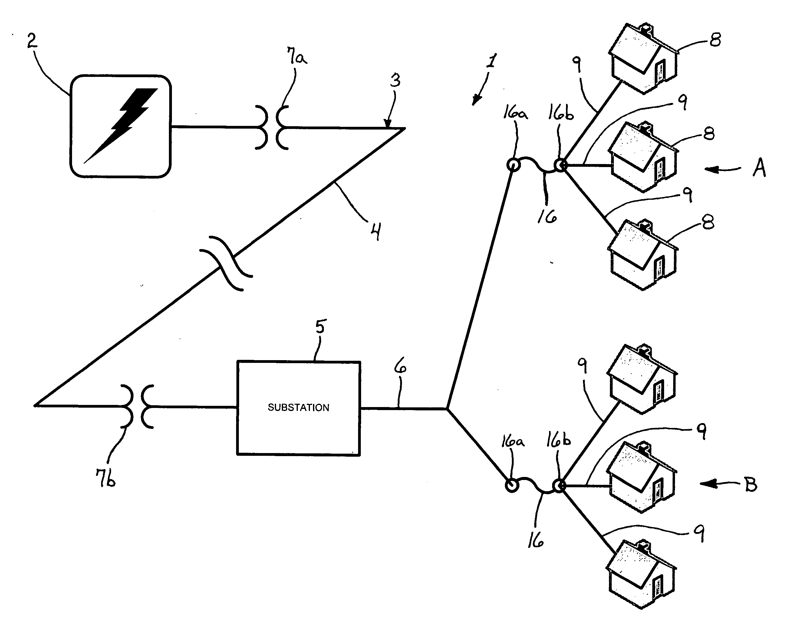
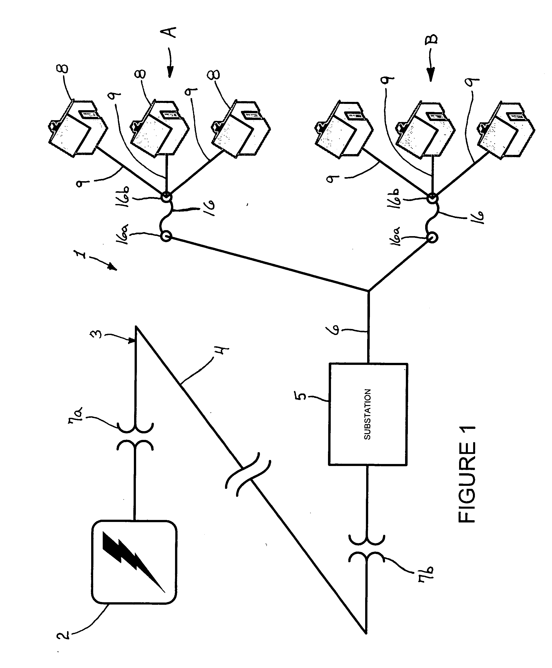
[0024]FIG. 1 schematically depicts a typical arrangement of an electric-energy distribution system 1. A generation facility 2 generates electric energy to be distributed to end users with a turbine, nuclear reactor, hydroelectric generator, or any other system for electric energy generation. As the generation facility 2 is the source of the electric energy, it is considered to be the furthermost “upstream” component of the distribution system 1. Based on the position that electric energy is conducted from the generation facility 2 to end users via a power grid 3, features such as a substation 5, transformers 7a, 7b, etc. . . . en...


PUM


Abstract

An adaptive relaying control system and method is disclosed for adapting coordination of protective measures provided to an electric-energy distribution system as a function of at least an ambient weather condition. A weather sensor senses the ambient weather condition within a region adjacent to at least a portion of the electric-energy distribution system. A control unit is operatively coupled to the weather sensor to receive a weather signal indicative of the ambient weather condition and determine whether a storm condition exists based at least in part on the weather signal. The control unit establishes a suitable control philosophy for adapting coordination of the protective measures provided to the electric-energy distribution system based at least in part on whether the storm condition exists.

Description

CROSS-REFERENCE TO RELATED APPLICATIONS [0001] This application claims the benefit of U.S. Provisional Application No. 60 / 734,003, filed on Nov. 4, 2005.BACKGROUND OF THE INVENTION [0002] 1. Field of the Invention [0003] The present invention is directed generally to a method and apparatus for controlling the distribution of electric energy, and more specifically, to a method and apparatus for adapting cooperation of protective measures provided to an electric-energy distribution system as a function of at least a sensed weather condition. [0004] 2. Description of Related Art [0005] Traditionally, electric energy has been transmitted away from generation facilities to be distributed to residential, industrial and commercial structures by a network of conducting wires commonly referred to as power lines. The network of power lines forms a portion of what is commonly referred to as a power grid. The power grid also includes the upstream generation facilities and substations disposed e...

Claims


Application Information

Patent Timeline
Patent Type & Authority Applications(United States)
IPC IPC(8): H02H3/00
CPCH02H1/04H02H3/006H02H3/07H02H5/00H02H5/005H02H7/30
Inventor FICKEY, KARL
Owner FIRSTENERGY CORP
Why Eureka
Try Eureka