AI technical title is built by Patsnap AI team. It summarizes the technical point description of the patent document.
a technology for lighted mirrors and vehicles, which is applied in the field of automotive lighting, can solve the problems that the manufacturers of mirror assemblies that have their current production of mirror assemblies tooled for incandescent light source applications have not been able to take full advantage of the recent developments in the use of non-incandescent light sources, and achieve the effect of efficient power generation and maximum power transfer efficiency
Inactive Publication Date: 2007-05-17
DONNELLY CORP
View PDF99 Cites 42 Cited by
Summary
Abstract
Description
Claims
Application Information
AI Technical Summary
This helps you quickly interpret patents by identifying the three key elements:
Problems solved by technology
Method used
Benefits of technology
Benefits of technology
[0018] In another aspect, the non-incandescent light source circuit further includes a polarity rectifier, such as a diode bridge rectifier, which eliminates the polarity of the light source module. In this manner, the light source unit can be plugged in with the connectors in either orientation without a need for a polarity indicator.
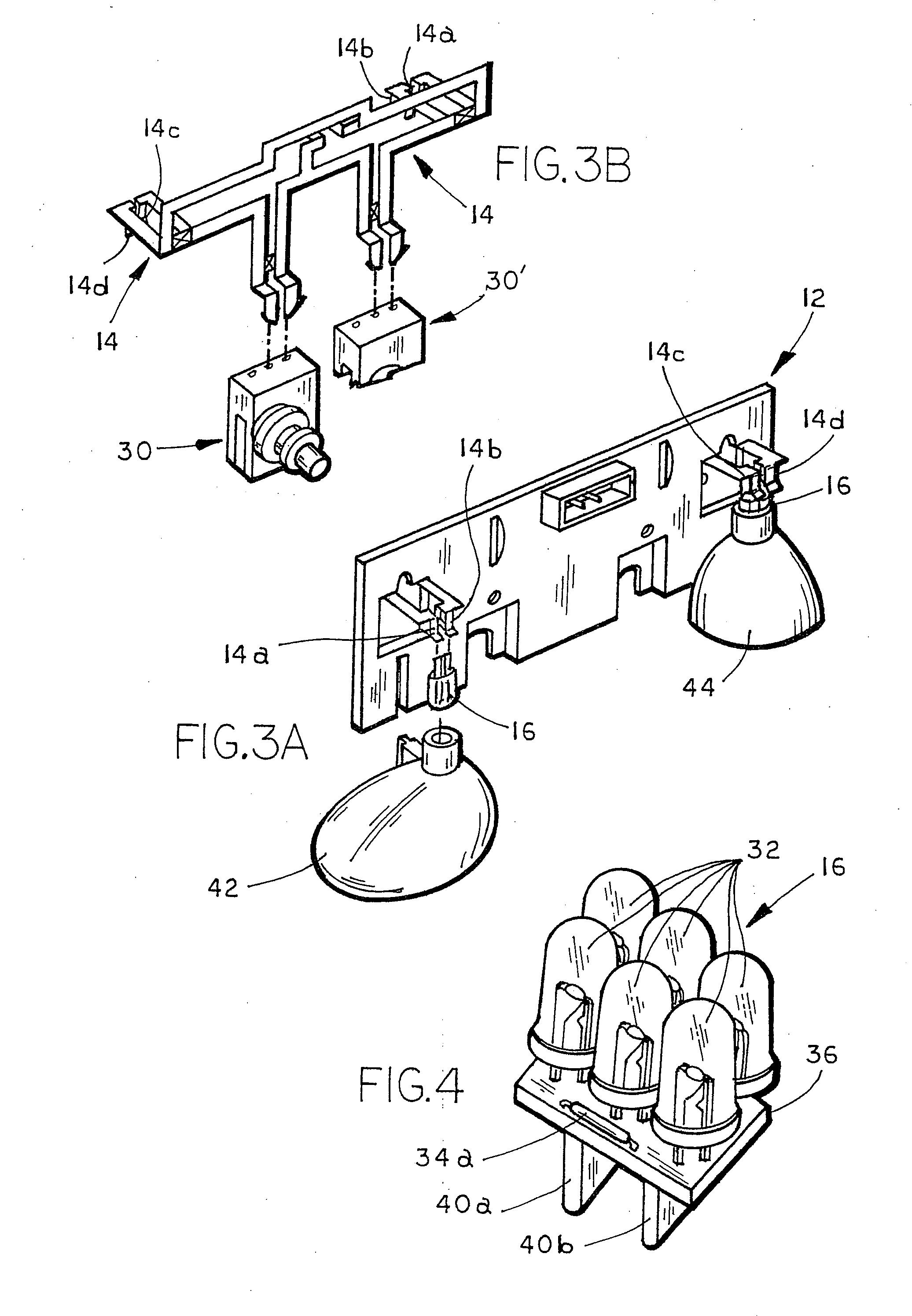
[0020] In one aspect, the non-incandescent light source of the non-incandescent light source unit comprises a plurality of light emitting diodes. For example, the circuit of the non-incandescent light source unit may include a silicon wafer or similar microelectronic chip element having the light emitting diodes established as junctions on the chip surface, as is known in the light emitting diode (LED) art. The chip may include a plurality of individual junctions forming the individual light emitting diodes. Optionally, the light emitting diodes are enclosed in a surround that functions both as an encapsulant to protect the LED junctions from environmental and mechanical damage and as an optical element (such as a lens and / or a diffuser) for light emitted by the LED junctions on the chip surface.
[0035] The present invention includes use of a direct current (DC) step-down voltage conversion element in order to allow a single high-intensity power LED (or at most two or three individual LEDs connected electrically in series or a plurality of individual LEDs connected electrically in parallel) be efficiently powered with maximum power transfer efficiency between the powering DC source (typically the vehicle battery or ignition system) and the LED being powered, and with minimum need to dissipate power as heat in a resistive element (such as a series power resistor capable of dissipating power of the level of about 1 watt and higher, and sometimes in conjunction with a heat sink / heat dissipater) and / or to use the like of pulse width modulation or similar circuitry to vary the duty cycle being applied to the individual LED being powered.
Problems solved by technology
Some manufacturers are slower to retool existing incandescent lighted mirror assembles to accommodate LEDs and, as a result, have and will continue to have a large inventory of mirror assemblies that are tooled for incandescent light sources.
When mirror assemblies are tooled for incandescent light sources, these mirror assemblies have heretofore been limited to using incandescent-light-source replacements for the incandescent light sources.
Therefore, mirror manufacturers that have their current production of mirror assemblies tooled for incandescent light source applications have not been able to take full advantage of the recent developments in the use of non-incandescent light sources.
Method used
Image
Click on the blue label to locate the original text in one second.
Reading with bidirectional positioning of images and text.
Examples
Embodiment Construction
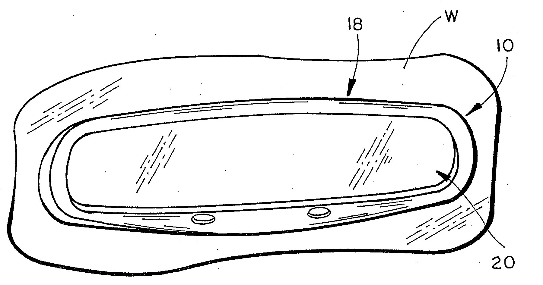
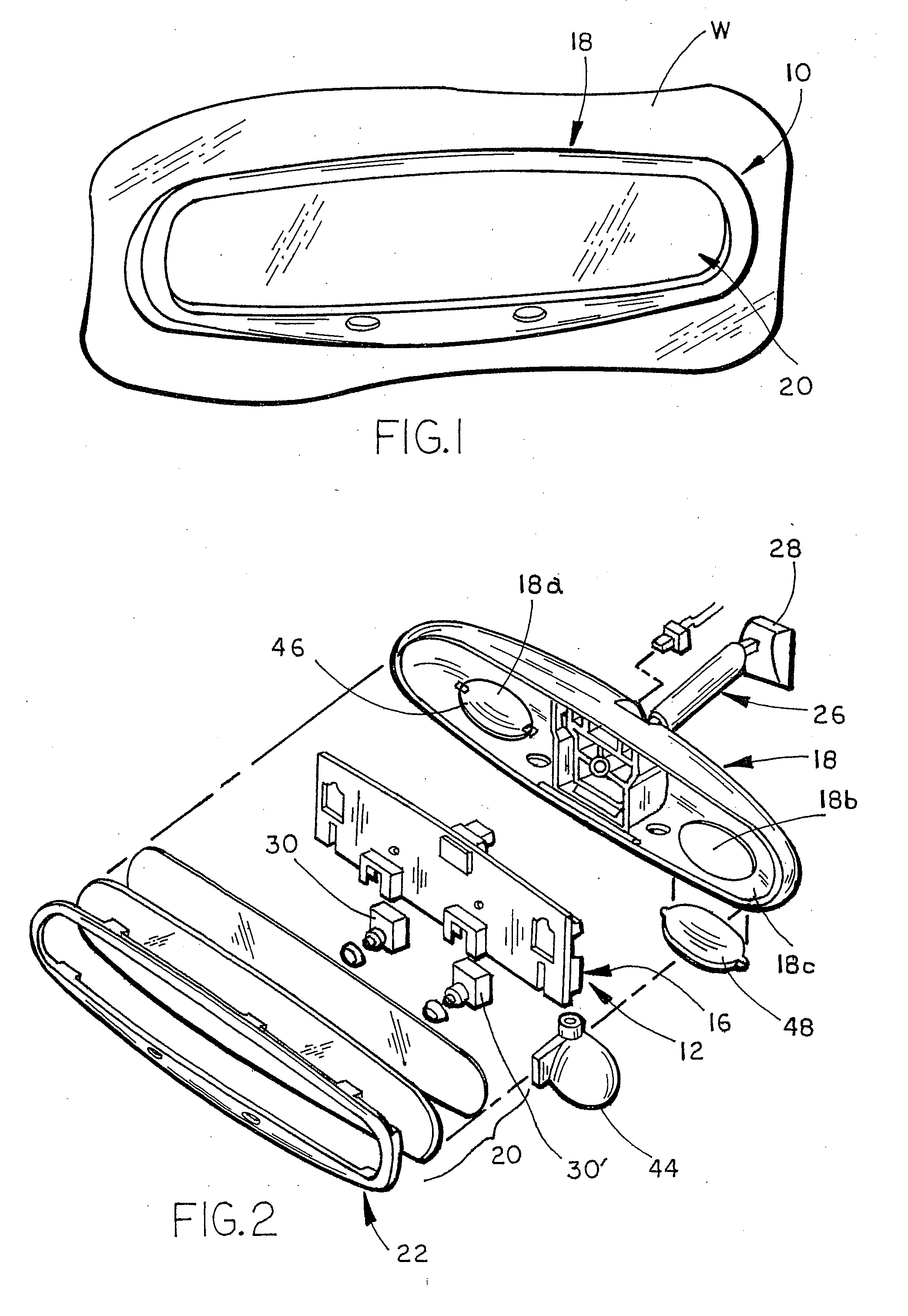
[0083] Referring to FIG. 1, the numeral 10 generally designates an interior rearview mirror assembly which incorporates at least one non-incandescent light source unit / module 16 of the present invention. As will be more fully described below, rearview mirror assembly 10 includes a carrier 12 with an incandescent light source circuit member 14 (FIG. 4) to which non-incandescent light source unit / module 16 is electrically coupled in an incandescent light source socket (formed by contact elements 14a, 14b or 14c, 14d). Thus, non-incandescent light source unit 16 provides a replacement for a conventional incandescent light source, such as a filament light bulb. Alternatively, light source unit 16 may be electrically coupled via connections or contacts to corresponding connectors or contacts of other circuits that are connected to the vehicle ignition battery. In this manner, light source unit 16 provides a compact and serviceable light source that can be used in a wide variety of applic...
PUM
Abstract
A lighting system for a vehicle comprises a sealed unitary light module including at least one high-intensity power light emitting diode operates with a luminous efficiency of at least about 7 lumens per watt when passing a forward current of at least about 350 milliamps and that emits a luminous flux of at least about 25 lumens when operated at its operating voltage. The sealed unitary light module is removable as a unit from the vehicle and includes a heat dissipating element and a lens.
Description
CROSS REFERENCE TO RELATED APPLICATIONS [0001] This application is a continuation of U.S. patent application Ser. No. 10 / 054,633, filed Jan. 22, 2002 (Attorney Docket DON01 P-962), which claims priority from and incorporates by reference herein in their entireties U.S. Provisional Application Ser. No. 60 / 346,733, filed Jan. 7, 2002, entitled IMPROVED VEHICULAR LIGHTING SYSTEM, by Applicants John 0. Lindahl and Niall R. Lynam (Attorney Docket No. DON01 P-956), U.S. Provisional Applications Ser. No. 60 / 263,680, filed Jan. 23, 2001 (Attorney Docket No. DON01 P-876); Ser. No. 60 / 271,466, filed Feb. 26,2001 (Attorney Docket No. DON01 P-882); and Ser. No. 60 / 315,384, filed Aug. 28, 2001 (Attorney Docket No. DON01 P-930), and which is a continuation-in-part of U.S. Utility patent application Ser. No. 09 / 793,002, entitled VIDEO MIRROR SYSTEMS INCORPORATING AN ACCESSORY MODULE, filed Feb. 26, 2001, now U.S. Pat. No. 6,690,268 (Attorney Docket No. DON01 P-869).TECHNICAL FIELD AND BACKGROUND O...
Claims
Application Information
Patent Timeline
Application Date:The date an application was filed.
Publication Date:The date a patent or application was officially published.
First Publication Date:The earliest publication date of a patent with the same application number.
Issue Date:Publication date of the patent grant document.
PCT Entry Date:The Entry date of PCT National Phase.
Estimated Expiry Date:The statutory expiry date of a patent right according to the Patent Law, and it is the longest term of protection that the patent right can achieve without the termination of the patent right due to other reasons(Term extension factor has been taken into account ).
Invalid Date:Actual expiry date is based on effective date or publication date of legal transaction data of invalid patent.
Patent Type & AuthorityApplications(United States)

