Intelligent negative pulse repairing charger

A charger and negative pulse technology, applied in the field of intelligent negative pulse repair chargers, can solve the problems of not meeting the needs of battery buyers, lack of a resting stage in the charging process, lack of negative pulse activation, etc. Compact, well-designed effect

Inactive Publication Date: 2011-04-20
南京金陵紫光系统工程有限公司
View PDF4 Cites 8 Cited by
  • Summary
  • Abstract
  • Description
  • Claims
  • Application Information

AI Technical Summary

Problems solved by technology

[0006] 2. The charging process lacks a rest period
[0007] 3. During the charging process, the lack of negative pulse activation, even if it is only 1% of the charge, will have an irreplaceab

Method used


Image

  • Intelligent negative pulse repairing charger
  • Intelligent negative pulse repairing charger
  • Intelligent negative pulse repairing charger

Examples


Embodiment Construction

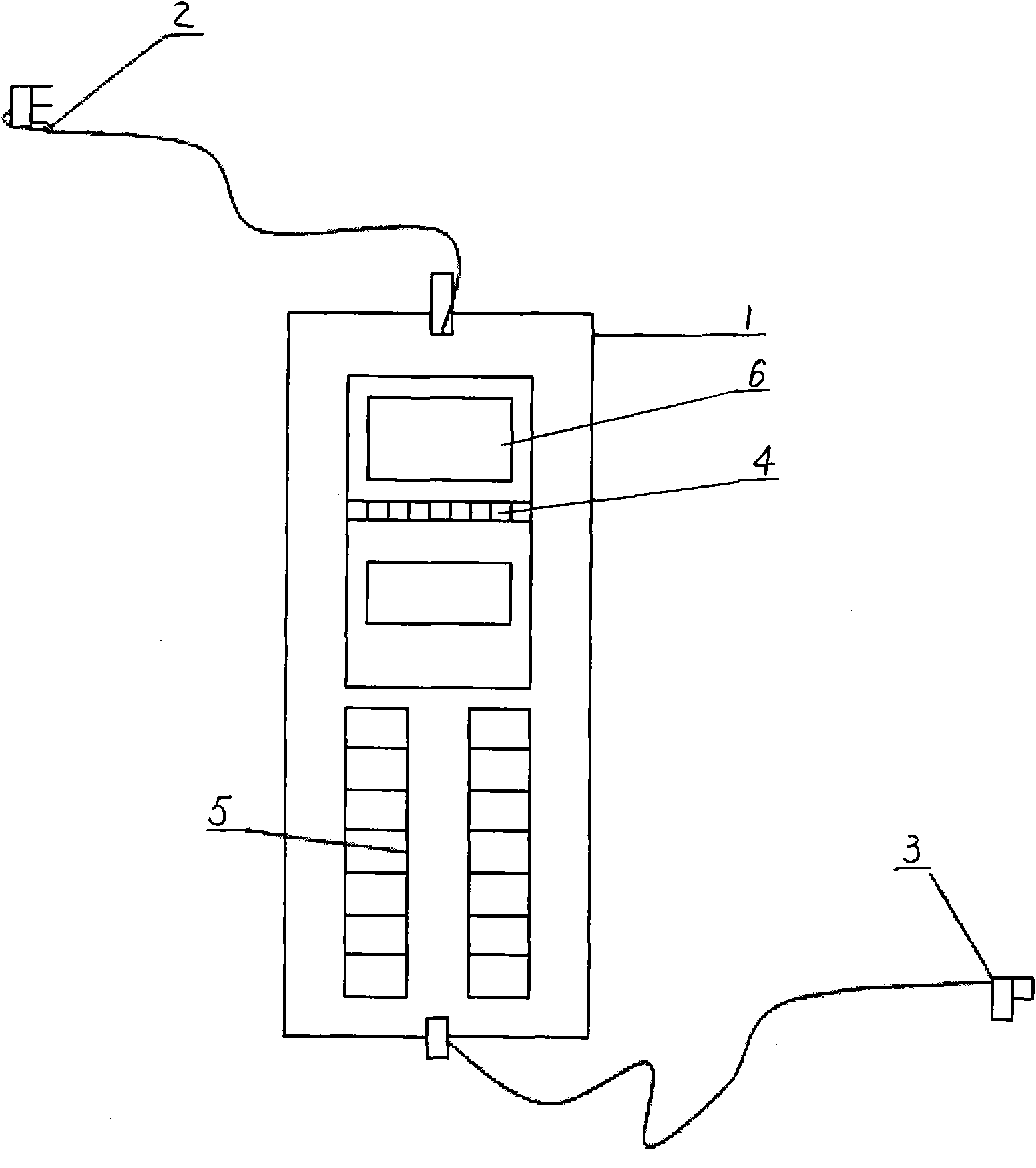
[0026] Reference attached Figure 1~3 , The intelligent negative pulse repair charger has a charger shell 1, a mains input plug 2, a charging output interface 3, a digital display window 6 and a light-emitting diode indicator 4. The light-emitting diode indicator 4 carries out red and green positive and negative pulse indications.

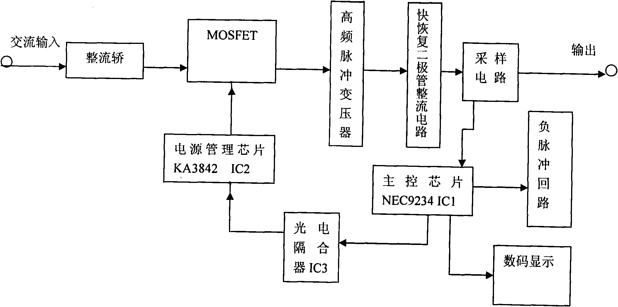
[0027] The charger shell 1 contains electronic circuit boards, electronic circuits and electronic components. The electronic circuits include rectifier bridge, MOSFET tube (field effect tube), main control chip (microcontroller) IC1, power management chip IC2, photoelectric isolator IC3, High frequency pulse transformer, fast recovery diode rectifier circuit, sampling circuit, negative pulse circuit, digital display.

[0028] The input end of the rectifier bridge is connected to the AC power supply, the output end of the rectifier is connected to the high-frequency pulse transformer through the MOSFET tube, and the output end of the high-frequency puls...


PUM


Abstract

The invention provides an intelligent negative pulse repairing charger, relating to the technology as follows: a switching power supply technology is adopted, a semiconductor power device is used as a switch, and commercial electricity is converted into voltage and current required by accumulator charging. The charger is provided with a charger case, and an electronic circuit comprises a rectifier bridge, an MOSFET (metal-oxide-semiconductor field effect transistor), a high frequency pulse transformer, a fast recovery diode rectifying circuit, a sampling circuit, a negative pulse loop, a main control chip IC1, a digital tube display, a photoelectric coupler IC3 and a power supply management chip IC2, wherein the input terminal of the rectifier bridge is connected with an alternating current power supply, the output terminal of the rectifier bridge is connected with the high frequency pulse transformer by the MOSFET, the output terminal of the high frequency pulse transformer is connected with the fast recovery diode rectifying circuit, the direct current output terminal of the fast recovery diode rectifying circuit is connected with the sampling circuit, a singlechip IC1 is connected with the photoelectric coupler IC3, the photoelectric coupler IC3 is connected with the management chip IC2, the power supply management chip IC2 is connected with the MOSFET, and the main control chip IC1 is also respectively connected with the sampling circuit, the negative pulse loop and the digital tube display.

Description

Technical field [0001] The intelligent negative pulse repair charger of the present invention relates to a switching power supply technology, using a semiconductor power device as a switch to convert the mains power into the voltage and current required for battery charging. As the capacity and stored electric energy of the battery are different, the required voltage and current are different at different charging stages. The intelligent negative pulse repair charger uses a single-chip microcomputer to accurately sample, and uses pulse width modulation (PWM) to control the opening of the electronic switch. It can control the output of switching power supply and realize closed-loop control. Background technique [0002] At present, a large number of popular three-stage chargers on the market divide the charging process into three stages: constant current, constant voltage, and floating charge. Take the 36V12Ah lead-acid battery pack that is used in my country's electric vehicle in...

Claims


Application Information

Patent Timeline
IPC IPC(8): H02J7/10
Inventor 袁光辉袁博李玲莉
Owner 南京金陵紫光系统工程有限公司
Why Eureka
Try Eureka