
Motor structure with built-in lens
a technology of motor structure and lens, which is applied in the direction of printers, instruments, camera focusing arrangement, etc., can solve the problems of increasing volume, adding cost and complexity to the camera lens module, etc., and achieves stable and accurate movement, high abrasion resistance, and reduced friction between the rotor and the bearing layer.
- Summary
- Abstract
- Description
- Claims
- Application Information
AI Technical Summary
Benefits of technology
Problems solved by technology
Method used
Image

Examples
Embodiment Construction
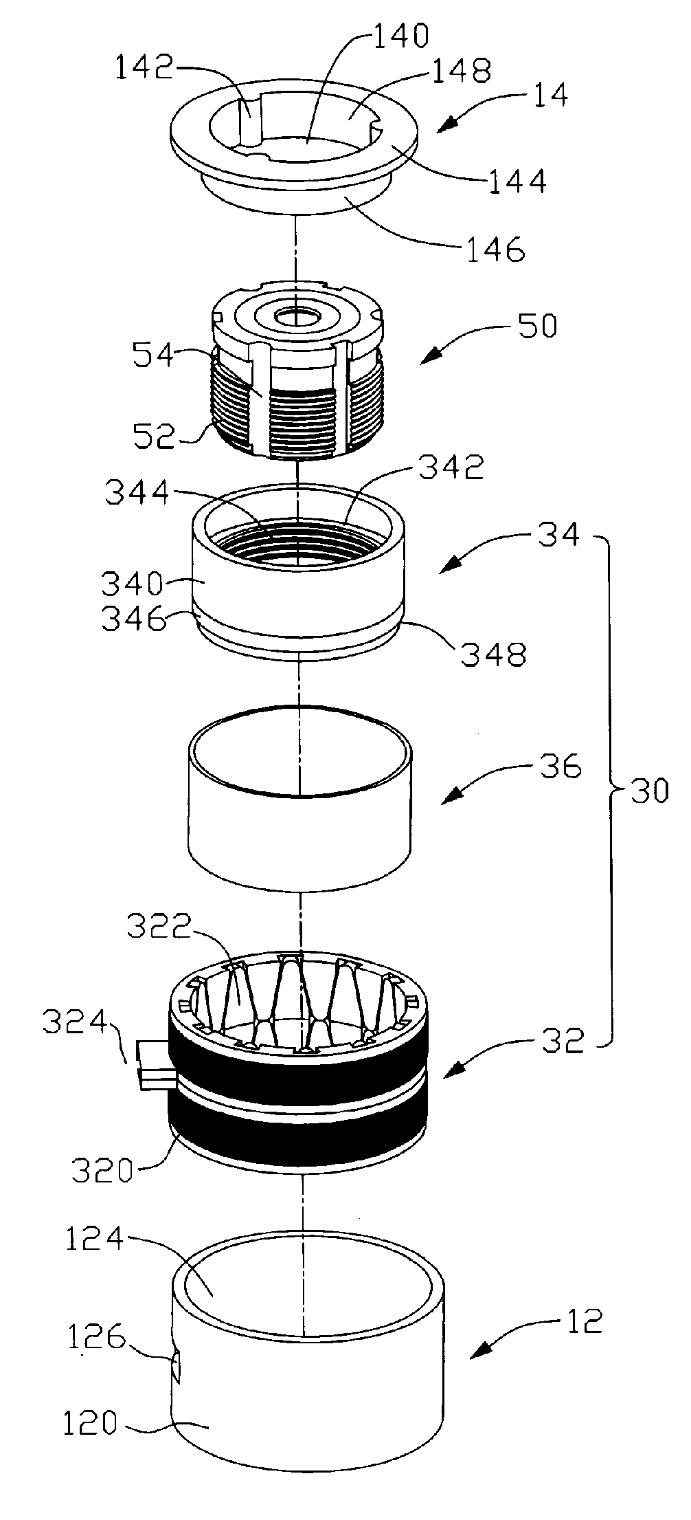
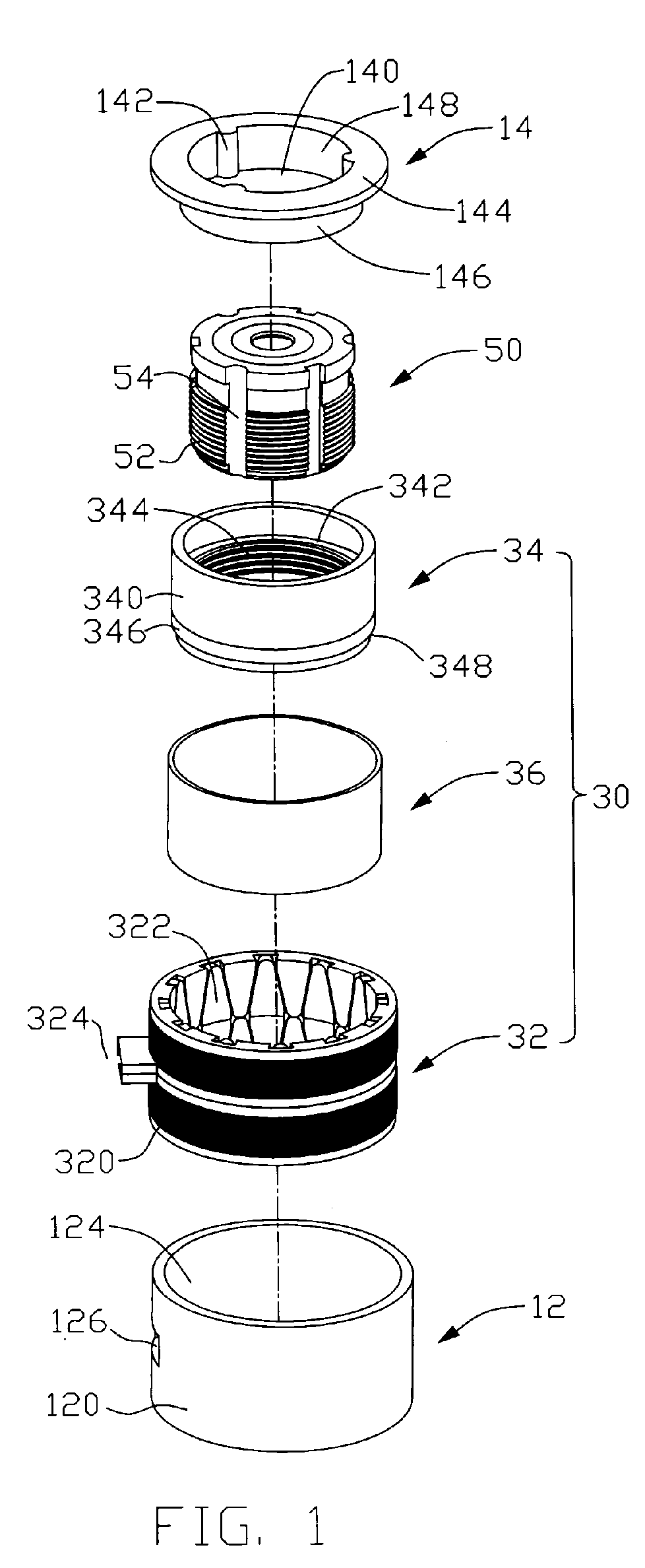
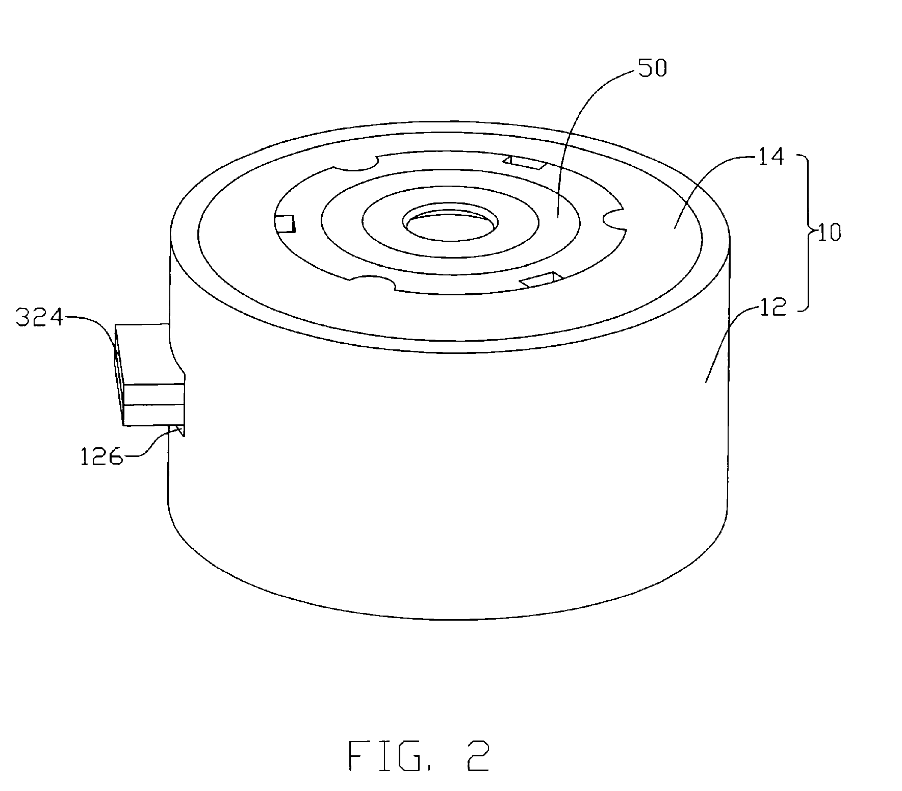
[0011] Referring to FIGS. 1 through 3, a motor structure with built-in lens according to a preferred embodiment includes a lens mount 10, a motor 30 received in the lens mount 10, and a lens unit 50 being drivable by the motor 30.
[0012] The lens mount 10 includes a bottom cover 12 and a top cover 14 located above and facing the bottom cover 12. The bottom cover 12 includes a ring-shaped basewall 122 and a sidewall 120 extending perpendicularly and upwardly from an outer-periphery of the basewall 122. An opening 124 is defined in the sidewall 120 above the basewall 122 for receiving the top cover 12. The top and bottom covers 14, 12 cooperatively define a column-shaped space (not labeled) therein when the top and bottom covers 14, 12 are assembled together. A passage 126 is defined in the sidewall 120 of the bottom cover 12 for extension of wires 324 of the motor 30 therethrough to connect the motor 30 with a power source (not shown). Circular hole 128 is defined in a central portio...
PUM
 Abstract
Description
Claims
Application Information