Detachable type Z-direction cutter assembly on machine tool

A dismantling and cutting tool technology, applied in the direction of manufacturing tools, metal processing machinery parts, clamping, etc., can solve the problems such as the inability to comprehensively use the precision transformation of machine tools, reduce or increase the Z-axis structure, and the belt is easily distorted and deformed. Processing performance and processing accuracy, high versatility, and the effect of reducing labor intensity

Pending Publication Date: 2019-10-08
SANMEN TONGSHUN RIVET
View PDF1 Cites 2 Cited by
  • Summary
  • Abstract
  • Description
  • Claims
  • Application Information

AI Technical Summary

Problems solved by technology

[0004] The machine tools in the above patent documents are equipped with double Z-axis and double-spindle structures. After assembly and fixation, a compound tool assembly structure is formed. The overall cost is relatively high, and the Z-axis structure cannot be reduced or increased according to needs, and the use is not flexible enough.
[0005] In addition, the Z-direction tool assembly in the prior art is mainly driven by a synchronous wheel synchronous belt and can only realize a single drilling function. Poor, no pollution, less noise advantages, but synchronous belt transmission also has its fatal disadvantages: the belt is easy to twist, deform, scratch, poor precision, not resistant to oil, small torque, small machine rigidity, easy to break the belt, etc.
In addition, due to the special requirements of its use environment, this type of Z-axis assembly is only suitable for specific machine tools, and cannot be comprehensively applied to the precision transformation of most machine tools

Method used


Image

  • Detachable type Z-direction cutter assembly on machine tool
  • Detachable type Z-direction cutter assembly on machine tool
  • Detachable type Z-direction cutter assembly on machine tool

Examples


Embodiment Construction

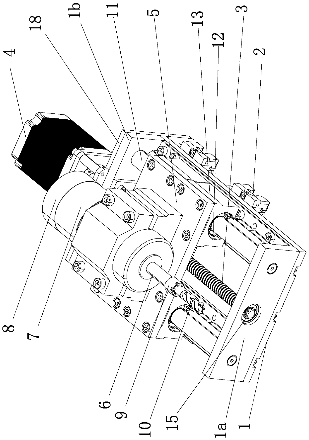
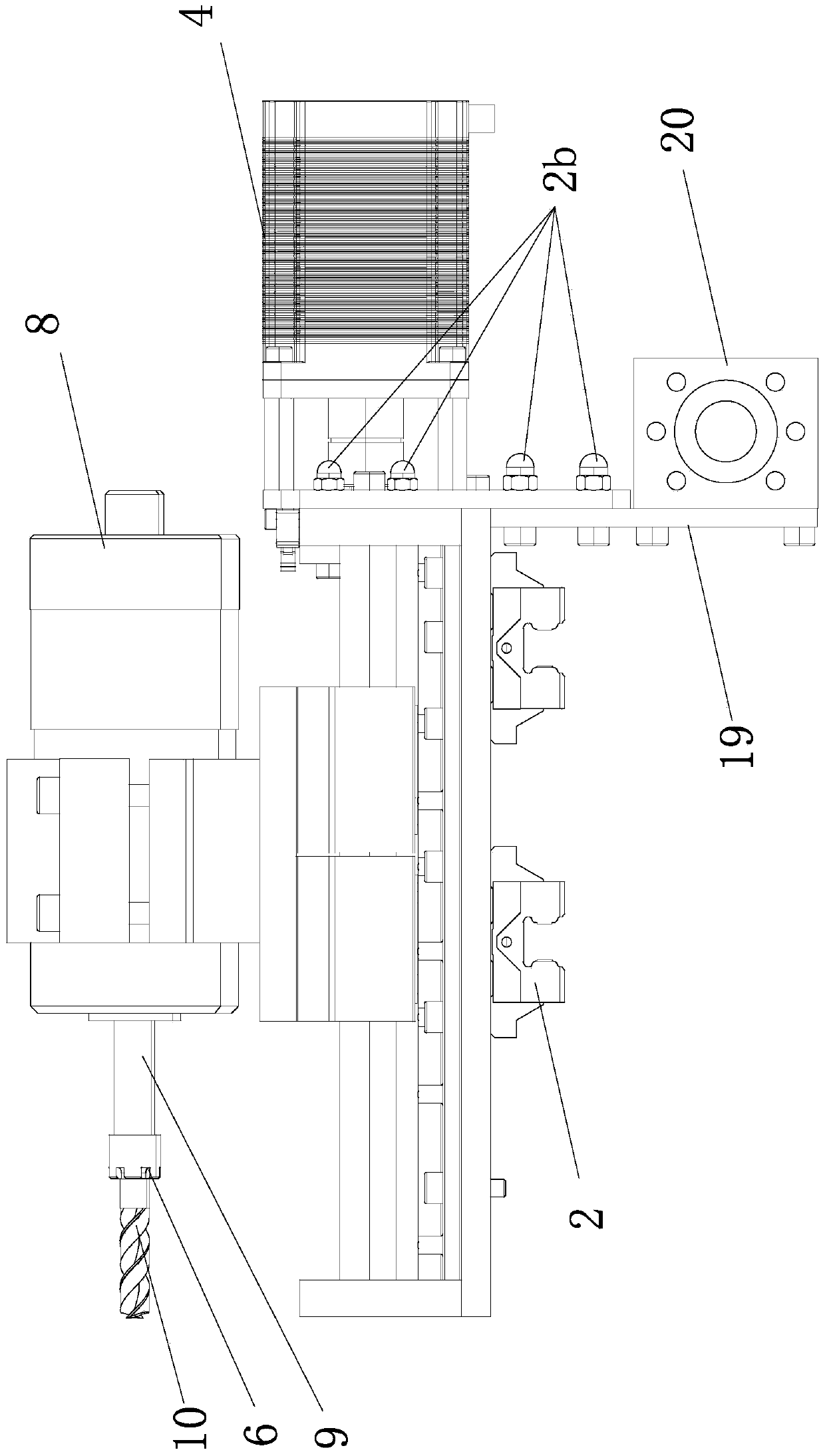
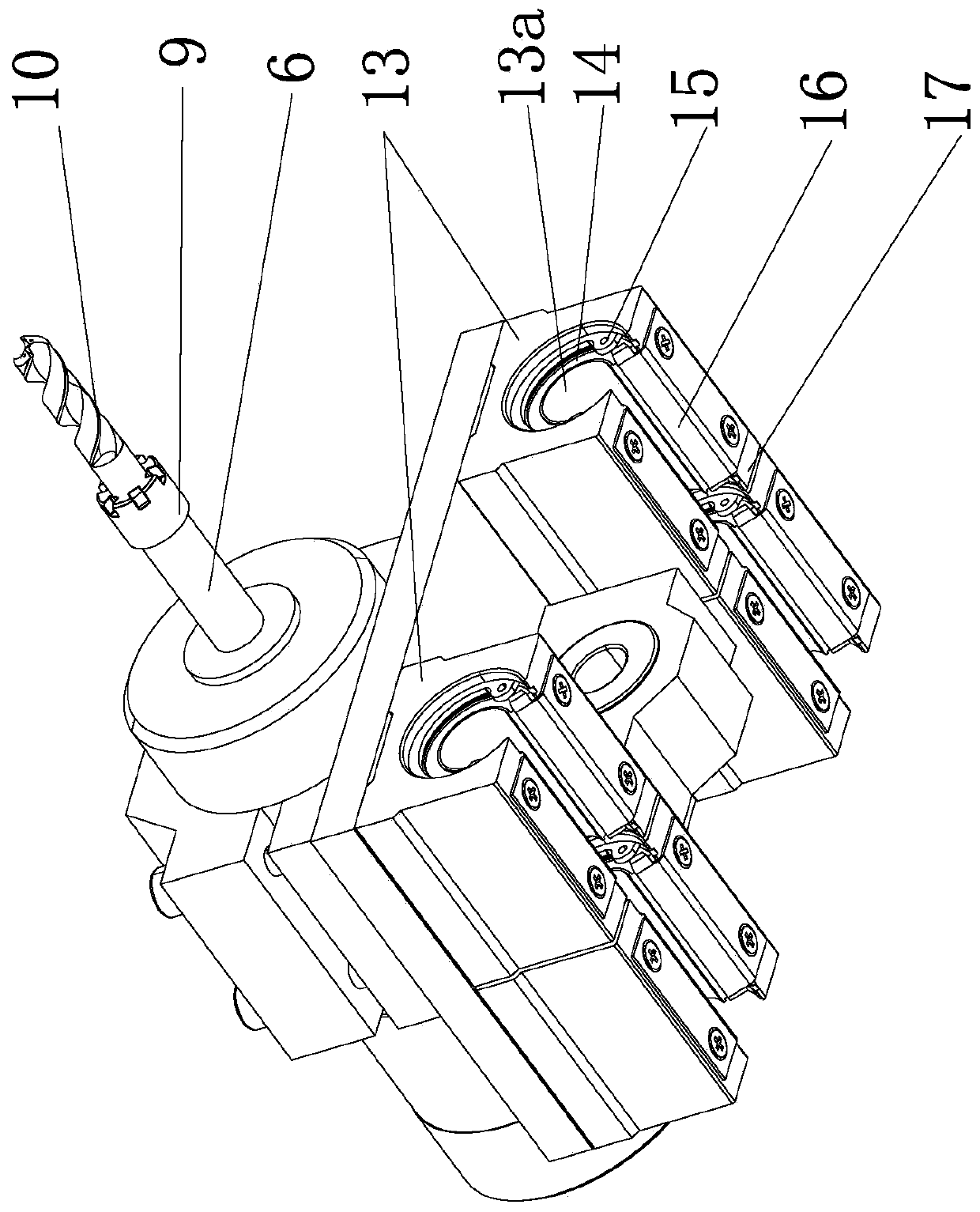
[0035] The following are specific embodiments of the present invention and in conjunction with the accompanying drawings, the technical solutions of the present invention are further described, but the present invention is not limited to these embodiments.

[0036] Such as Figure 1 to Figure 5 As shown, the detachable Z-direction tool assembly on this machine tool includes a base 1, and a fixed block assembly 2 is fixed on one side of the base 1; the fixed block assembly 2 includes a fixed seat 21 fixed on the side of the base 1 and a fixed On the cross rib plate fixing block 22 on the fixed seat 21, a wedge-shaped groove 22a is provided on the side of the cross rib plate fixing block 22; the other side of the base 1 is provided with a rotatable screw 3, and one end of the base 1 is fixed with A servo motor 4 capable of driving the lead screw 3 to rotate, the lead screw 3 is threadedly connected with a slide seat 5, the slide seat 5 is provided with a tool holder 6 and a driv...


PUM


Abstract

The invention provides a detachable type Z-direction cutter assembly on a machine tool and belongs to the technical field of machine tool equipment. By means of the detachable type Z-direction cutterassembly on the machine tool, the technical problem that the Z-direction cutter assembly on an existing machine tool is high in the cost and inconvenient to use is solved. The Z-direction cutter assembly comprises a base. Fixing block assemblies are fixedly arranged on one side of the base. A rotatable screw is arranged on the other side of the base. A servo motor by which the screw can be drivento rotate is fixedly arranged at one end of the base. A sliding base is in threaded connection with the screw. A cutter fixing sleeve and a driving motor by which the cutter fixing sleeve is driven torotate are arranged on the sliding base. A synchronizing wheel is further arranged on the output shaft of the driving motor. A cutter is fixed to an end of the cutter fixing sleeve through a cutter fixing lock. The axis direction of the screw is consistent with the axis direction of the cutter fixing sleeve. By means of the detachable type Z-direction cutter assembly on the machine tool, existingmachine tool equipment can be conveniently reformed; multiple Z-direction cutter assemblies can also be used simultaneously; the Z-direction cutter assembly is relatively flexible, convenient to assemble and high in universality; and the cost is saved.

Description

technical field [0001] The invention belongs to the technical field of machine tools and relates to a tool assembly on a machine tool, in particular to a detachable Z-direction tool assembly on a machine tool. Background technique [0002] Machine tools are equipment used to process and manufacture mechanical parts. With the improvement of production technology, CNC machine tools are more and more widely used. CNC machine tools are usually composed of control systems, servo systems, detection systems, and mechanical transmission systems. The control system is used for the calculation, management and control of the CNC machine tool. Data is obtained through the input medium, and the data is interpreted and calculated and has an effect on the machine tool; the servo system drives the machine tool according to the instructions of the control system, so that the tools and parts execute the CNC code regulations. The movement of the machine tool; the detection system is used to de...

Claims


Application Information

Patent Timeline
Patent Type & Authority Applications(China)
IPC IPC(8): B23Q3/00B23Q5/40
CPCB23Q3/00B23Q5/40B23Q5/402
Inventor 李政冀郑士旺
Owner SANMEN TONGSHUN RIVET
Why Eureka
Try Eureka