
Image fixing apparatus

a technology of fixing apparatus and fixing plate, which is applied in the direction of electrographic process apparatus, instruments, optics, etc., can solve the problems of deteriorating endurance of pressure rollers, conflicting requirements, and deteriorating so as to improve the fixability of toner images

Active Publication Date: 2007-05-17
HEWLETT PACKARD DEV CO LP
View PDF53 Cites 19 Cited by
  • Summary
  • Abstract
  • Description
  • Claims
  • Application Information

AI Technical Summary

Benefits of technology

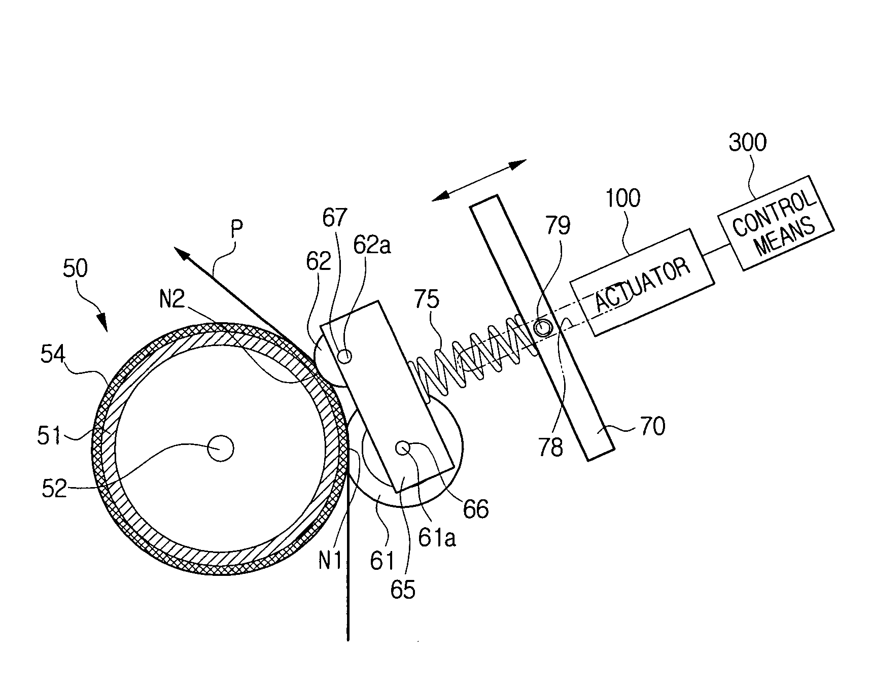
[0024] An object of the present invention is to provide an image fixing apparatus and a method of controlling the same, which adjust the compressive forces of plural pressure rollers of the image fixing apparatus according to one or more parameters of a record medium and / or density of a toner image, thereby improving the fixability of the toner image.

Problems solved by technology

In many cases, however, the above-mentioned requirements may be in conflict with each other.
To the contrary, if the temperature of the heat roller is reduced, the fixability of the toner image is deteriorated.
However, the endurance of the pressure roller may be deteriorated.
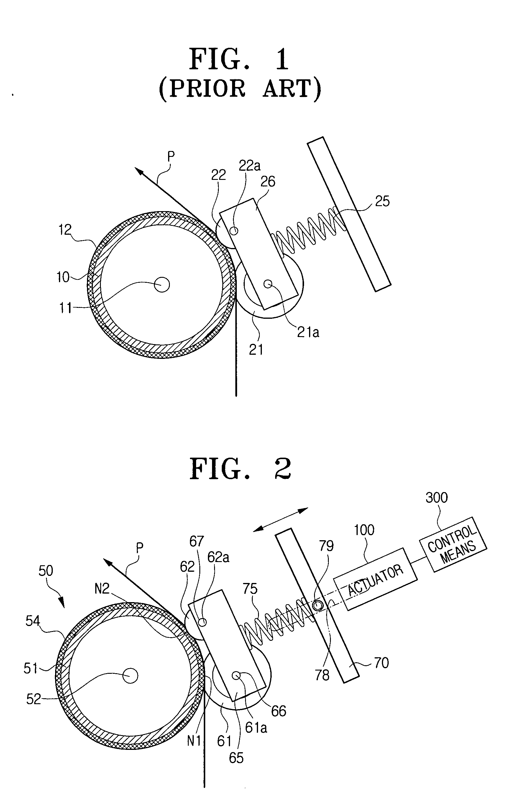
However, the above-mentioned prior art has a limit in that because the magnitudes and / or the directions of the compressive forces to be applied by the first and second pressure rollers 21 and 22 are specified and fixed in such a manner as to be suitable for ordinary print papers, it is extremely difficult to properly cope with parameters of a certain record medium (for example, thickness, quality of material, and any other characteristic of the record medium), density of a toner image to be deposited to the record medium, or the like.

Method used


Image

  • Image fixing apparatus
  • Image fixing apparatus
  • Image fixing apparatus

Examples


third embodiment

[0136] The third embodiment is technically characterized by the fact that the relative ratio of the compressive forces applied to the plural pressure rollers 61 and 62 may be adjusted because the support member 70 is provided in such a manner as to be pivotable about a pivot point 73 in relation to a frame (not shown) of an image fixing apparatus.

[0137] By the pivotal movement of the support member 70, the plural compression portions 76 and 77 disposed between the support member 70 and the bushing member 65 may variably apply compressive forces, so that the relative ratio of the compressive forces applied to the first and second pressure rollers 61 and 62 may be adjusted. In FIG. 4, when the support member 70 is pivoted in the direction indicated by arrow A from its reference position (for example, neutral position where the compressive forces applied by the first and second compression portions 76 and 77 are substantially equal to each other), the compressive force applied by the s...

fourth exemplary embodiment

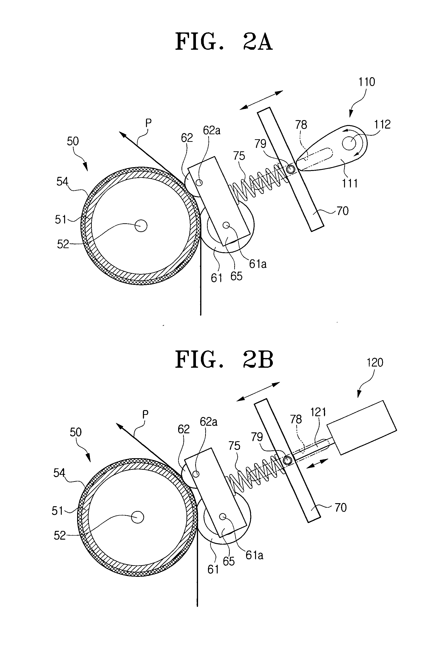
[0165] The actuator 100 applied to the third exemplary embodiment is not limited to the first to the fourth specific forms of actuators, and various types of actuators are applicable to the fourth exemplary embodiment to pivot the support member 70 about the pivot point 73.

[0166] FIGS. 5 to 5E conceptually show a fourth exemplary embodiment of the present invention.

[0167] As shown in FIG. 5, the fourth exemplary embodiment of the present invention includes a heat roller 50, plural pressure rollers 61 and 62, and compression portions 76 and 77 for compressing the pressure rollers 61 and 62.

[0168] The compression portions 76 and 77 are resiliently disposed between bushing member 65 and support member 70, the bushing member 65 being provided in such a manner as to be pivotable about a pivot point 69, which is provided on the bushing member 65. The support member 70 is fixedly provided on a frame (not shown) of an image fixing apparatus.

[0169] The third exemplary embodiment is config...


PUM


Abstract

An image fixing apparatus includes a heat roller, and plural pressure rollers, which rotationally contact the surface of the heat roller by a compression unit. The plural pressure rollers are provided in such a manner that the compressive forces thereof may be adjusted. With this construction, the fixability of a toner image is improved and crumples, wrinkles, and wrap jam that may be produced when a toner image is fixed are substantially prevented.

Description

CROSS-REFERENCE TO RELATED APPLICATIONS [0001] This application claims the benefit under 35 §119(a) of Korean Patent Application Nos. 2005-108751 and 2005-121613, filed on Nov. 14, 2005 and Dec. 12, 2005, respectively, in the Korean Intellectual Property Office, the entire disclosures of both of which are hereby incorporated by reference. BACKGROUND OF THE INVENTION [0002] 1. Field of the Invention [0003] The present invention relates to an image fixing apparatus for fixing a toner image to a record medium and a method of controlling the same. [0004] 2. Description of the Related Art [0005] As is well-known in the art, an electrophotographic image forming apparatus, such as a laser beam printer, an LED printer, a digital copying machine, a facsimile and the like, is an appliance for transferring image signals to a record medium as a visual image according to digital signals inputted from a computer or a scanner. [0006] Specifically referring to the operation of such an image forming...

Claims


Application Information

Patent Timeline
Patent Type & Authority Applications(United States)
IPC IPC(8): G03G15/20
CPCG03G15/206G03G2215/20
Inventor KIM, JIN-YOONYOON, YOUNG-MIN
Owner HEWLETT PACKARD DEV CO LP
Learn More