Turning control apparatus for vehicle

Active Publication Date: 2007-05-17
MITSUBISHI MOTORS CORP
View PDF3 Cites 19 Cited by
  • Summary
  • Abstract
  • Description
  • Claims
  • Application Information

AI Technical Summary

Benefits of technology

[0016] The present invention has been developed in consideration of this situation, and it is therefore an object of the invention to provide a turning control apparatus for a vehicle, which apparatus is capable of improving turning ability and avoiding degradation acceleration.
[0017] For this purpose, in accordance with an aspect of the present invention, there is provided a turning control apparatus for a vehicle comprising a first yaw controller for adjusting at least one of driving torque of a left wheel and a right wheel; a second yaw controller for adjusting a speed differing between a front wheel and a rear wheel; and an integrated yaw controller for controlling yaw momentum of the vehicle by managing the first yaw controller and the second yaw controller, wherein when the yaw of the vehicle should be reduced, the integrated yaw controller controls the first yaw controller so as to decrease the driving torque of a inside wheel, which is one of the right wheel and left wheel and is near to a c

Problems solved by technology

However, it is difficult to eliminate over-steer of vehicles during turning maneuvers by such techniques as controlling the left-right-wheel driving torques in the related document 1.
In this situation, the inside wheel must be skid easily even if the inside wheel's driving torque is increased, therefore it is difficult to generate sufficient yaw of the vehicle to eliminate over-steering.
As explained above, it is difficult to eliminate not only over-steering but also under-st

Method used


Image

  • Turning control apparatus for vehicle
  • Turning control apparatus for vehicle
  • Turning control apparatus for vehicle

Examples


Embodiment Construction

[0025] The embodiment of present invention will now be described with reference to the accompanying drawings.

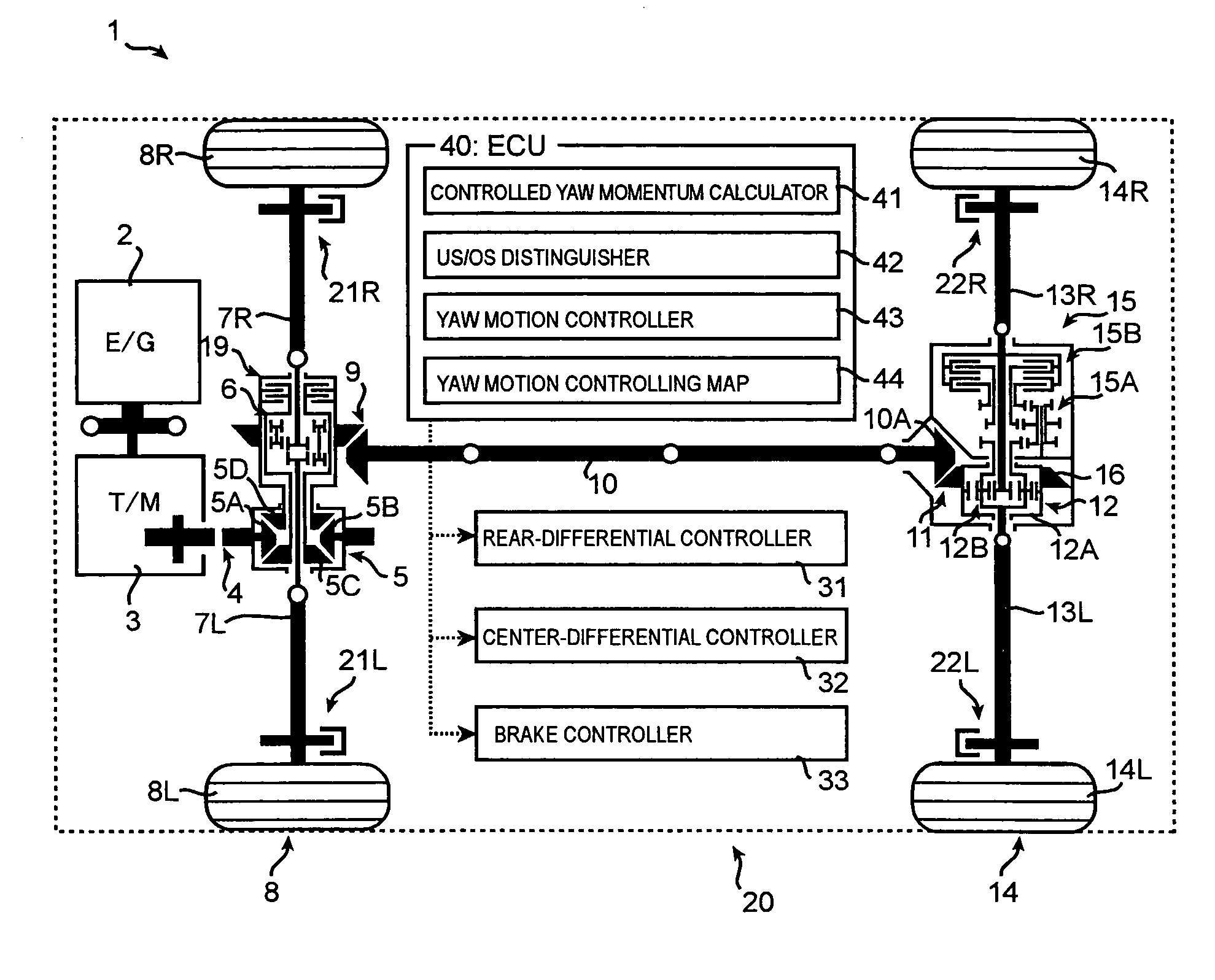
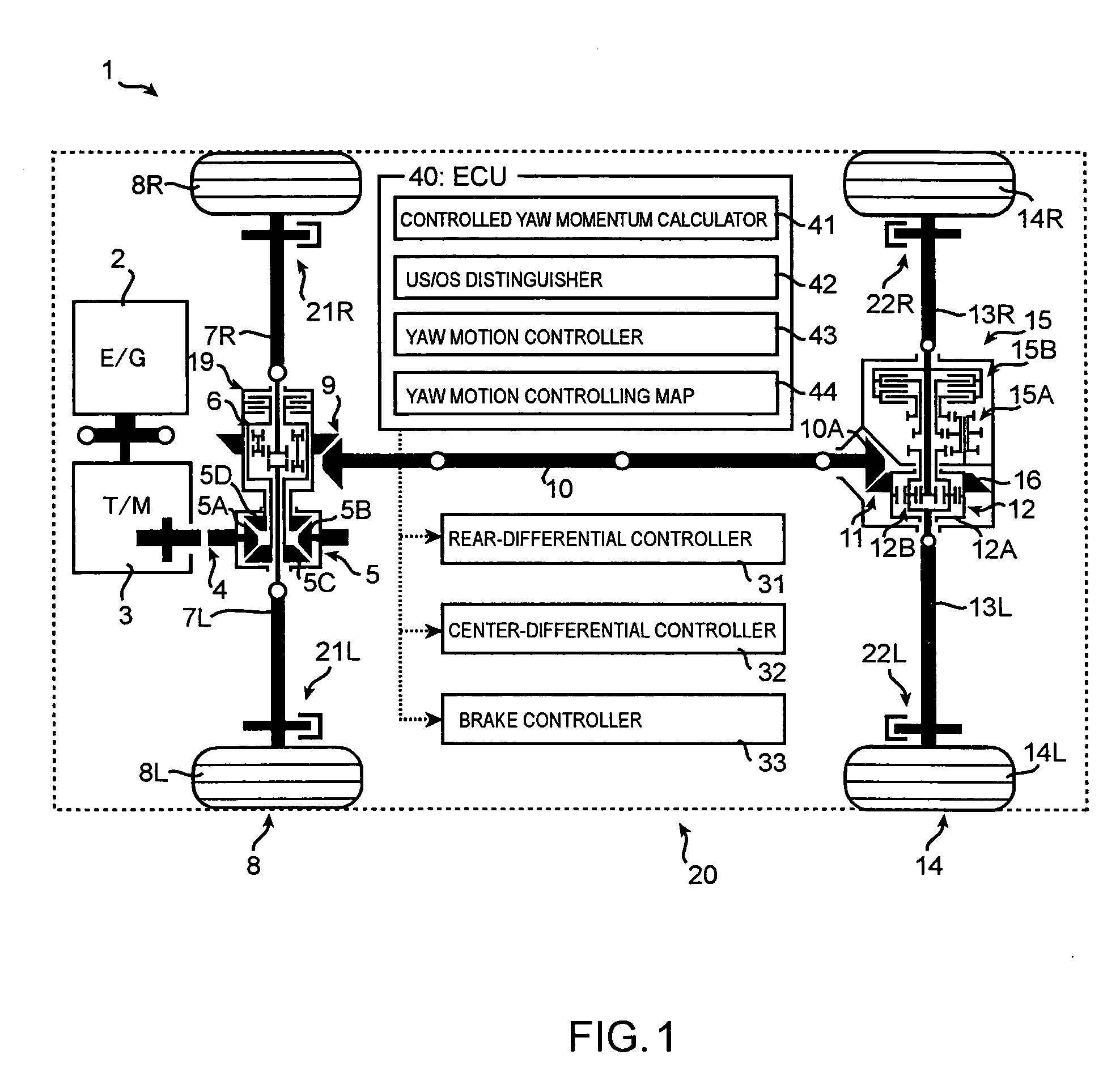
[0026] As shown in FIG. 1, an engine 2 is mounted on a vehicle 1. The torque output from the engine 2 is transmitted to a center differential 5 via transmission 3 and intermediate gear mechanism 4. The center differential 5 has a front-rear wheels limiting mechanism 19 which will be described later.

[0027] The output torque from the center differential 5 is individually transmitted to a front-right wheel 8R and a front-left wheel 8L via a front differential 6 and each of shafts 7L and 7R. And the torque output from the differential 5 is individually transmitted to a rear-right wheel 14R and rear-left wheel 14L via a front-hypoid gear mechanism 9, a propeller shaft 10, a rear-hypoid gear mechanism 11, a rear-differential 12 and each of shafts 13R and 13L. The rear-differential 12 has a right-left wheel limiting mechanism 15 which will be described later.

[0028] The front-diff...


PUM


Abstract

The present invention provides a turning control apparatus for a vehicle to improve turning ability and to avoid degradation of acceleration ability. The turning control apparatus comprises a first yaw controller for adjusting at least one of driving torque of a left wheel and a right wheel; a second yaw controller for adjusting a speeds difference between a front wheel and a rear wheel; and an integrated yaw controller for controlling yaw momentum of the vehicle by managing the first and second yaw controller, wherein when the yaw of the vehicle should be reduced, the integrated yaw controller controls the first yaw controller so as to decrease the driving torque of a inside wheel, which is one of the right and left wheel and is near to a center axis of turning, and the second yaw controller so as to decrease the speeds difference between the front and rear wheel.

Description

BACKGROUND OF THE INVENTION [0001] (1) Field of the Invention [0002] The present invention relates to a turning control apparatus for a vehicle. [0003] (2) Description of Related Art [0004] Techniques have been developed that for improving safety of vehicles by achieving vehicle-stability during turning maneuvers. For example, the following related document 1 discloses that feedback control, based on the yaw-rate of the vehicle, for both the torque that varies between the left and right wheels and also the different brake pressures of individual wheels. [0005] Further, the following related document 2 discloses that another feedback control for the Electrical Controlled Limited Slip Differential Unit of the center differential varies the speeds between the front and rear wheels. [0006] [Related Document 1] JP H9-86378 Laid-Open Publication [0007] [Related Document 2] JP 2853474 Patent Publication [0008] However, it is difficult to eliminate over-steer of vehicles during turning mane...

Claims


Application Information

Patent Timeline
IPC IPC(8): G06F19/00B60T8/1755B60W10/10B60W10/12B60W10/14B60W10/16B60W10/18B60W10/188F16H48/05F16H48/10F16H48/22F16H48/30F16H48/32F16H48/36F16H48/38
CPCB60K17/043B60K17/20B60K23/04B60K23/0808B60T8/1755B60T2201/14B60W10/14B60W10/16B60W10/184B60W30/02B60W2710/12B60W2720/14B60W2720/403
Inventor MIURA, TAKAMISUZUKI, KEIJI
Owner MITSUBISHI MOTORS CORP
Why Eureka
Try Eureka