Tool containment system

a technology of tool containment and tool, which is applied in the field of tool containment system, can solve the problems of unresolved problems in the use of power tools, lack of fastening means to which a tether can be connected, and the portability of power tools, especially cordless power tools, which may have no means by which a tether can be fastened, so as to reduce the travel of tools

Inactive Publication Date: 2007-05-24
CASTLE MOUNTAIN ENTERPRISES
View PDF12 Cites 41 Cited by
  • Summary
  • Abstract
  • Description
  • Claims
  • Application Information

AI Technical Summary

Benefits of technology

[0006] Accordingly, a broad object of the invention can be to provide a flexible member which engages a part of the external surface of a tool to provide an attachment location for a tether which can reduce travel of the tool when it drops, falls, or may otherwise be urged to travel.

Problems solved by technology

While power tools may be convenient to use, especially cordless power tools using rechargeable battery supplies, there remain substantial unresolved problems in the use of such power tools.
A significant problem with the use of portable power tools can be the lack of a fastening means to which a tether can be connected.
Portability of power tools, especially cordless power tools, which may have no means by which a tether can be fastened can be a hazard to persons and property when they drop, fall, or are otherwise urged to travel.
This can be particularly true of power tools having rechargeable battery supplies where both the tool and the battery supply have sufficient mass to cause injury to persons or property upon impact.
Additionally, when the tool becomes uncoupled from the battery supply, both the tool, which presents a hollow interior, and the battery supply, which typically presents projection which mates with the hollow interior of the tool, can be the source of additional injury to persons or generate additional property damage.
Moreover, when the tool becomes separated from the battery supply both the tool and the battery supply can become more susceptible to damage.
While cordless power tools have been available for many years, it appears that tool manufactures have not yet addressed the problem of limiting the travel of the tool or the uncoupled battery supply.
Another problem with the increased portability of power tools can be the lack of means to retain replacement parts such as drill bits, saw blades, screwdriver bits, or the like proximate to the tool.
Similarly, there can be a lack of means to retain certain hardware proximate to the tool, such as screws, nails, rivets, staples, or the like

Method used


Image

  • Tool containment system
  • Tool containment system
  • Tool containment system

Examples


Embodiment Construction

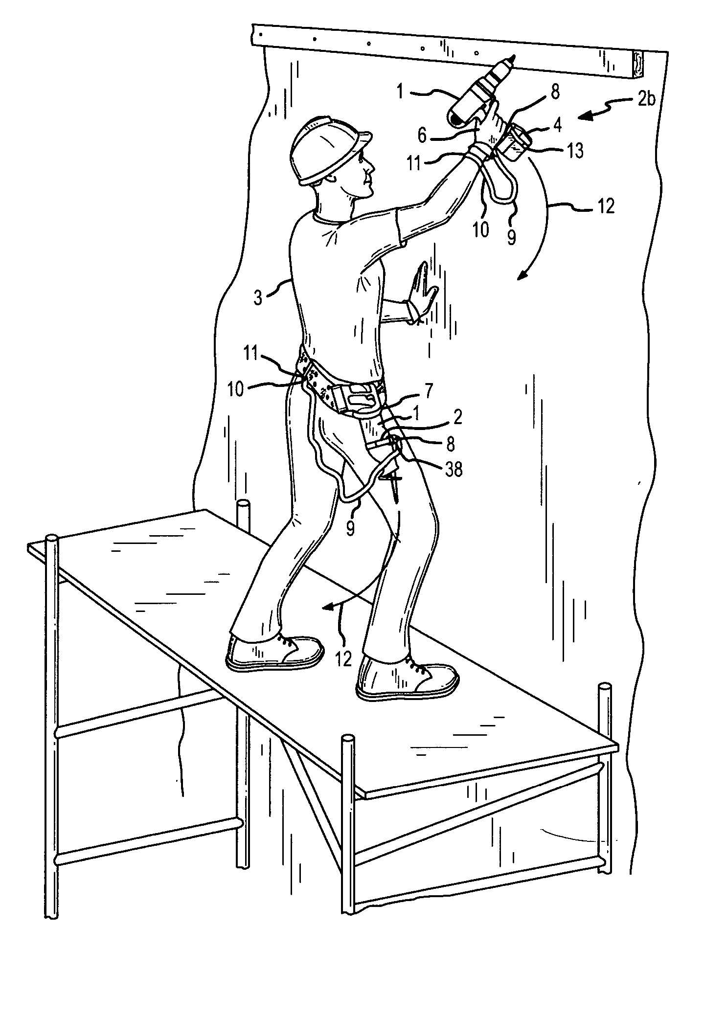
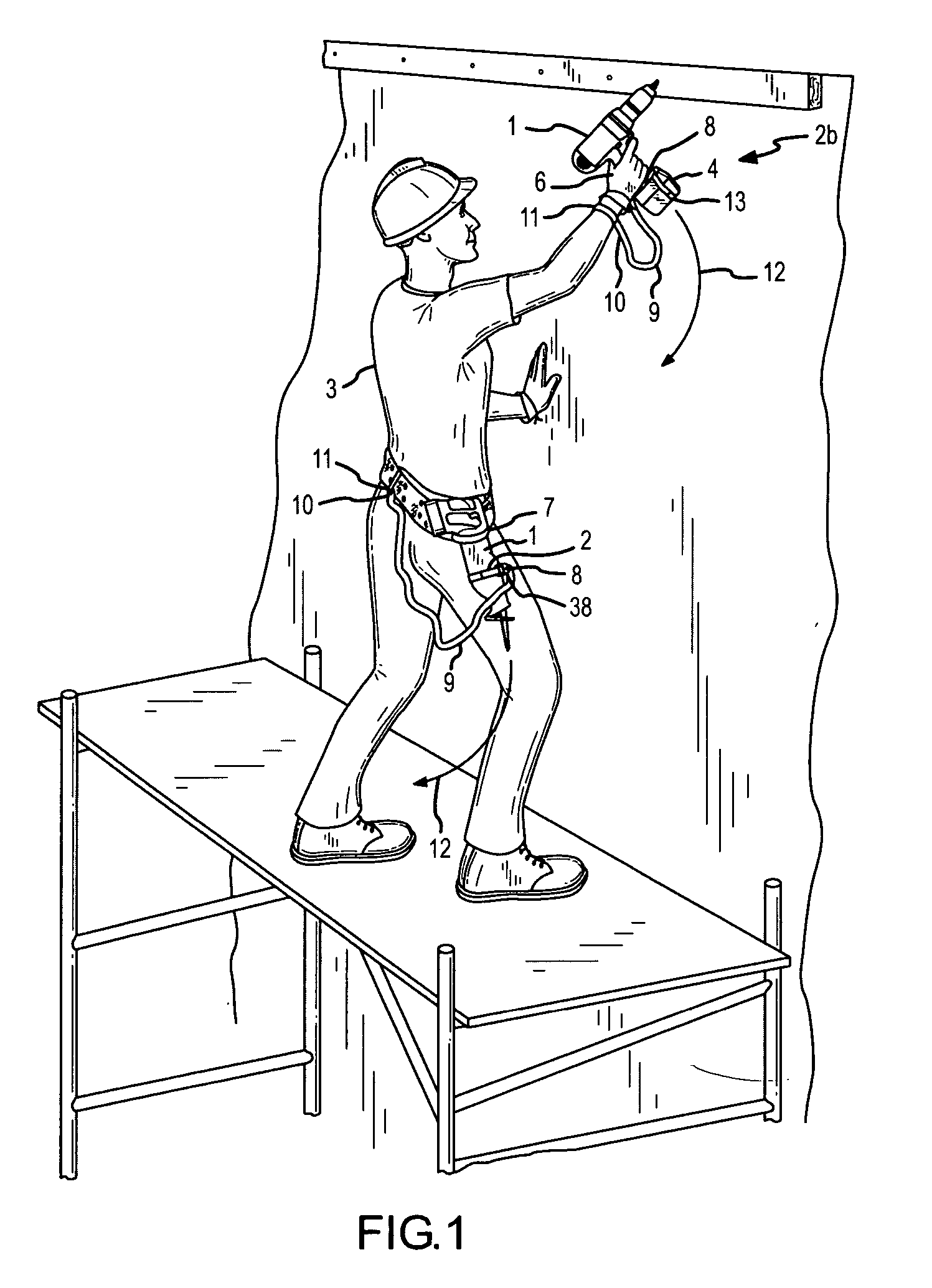
[0049] A tool containment system provides various configurations of a flexible member each of which can engage a part of the external surface of a tool to provide connection means for a tether to limit travel of the tool, or to oppose disassembly of tool components, or both.

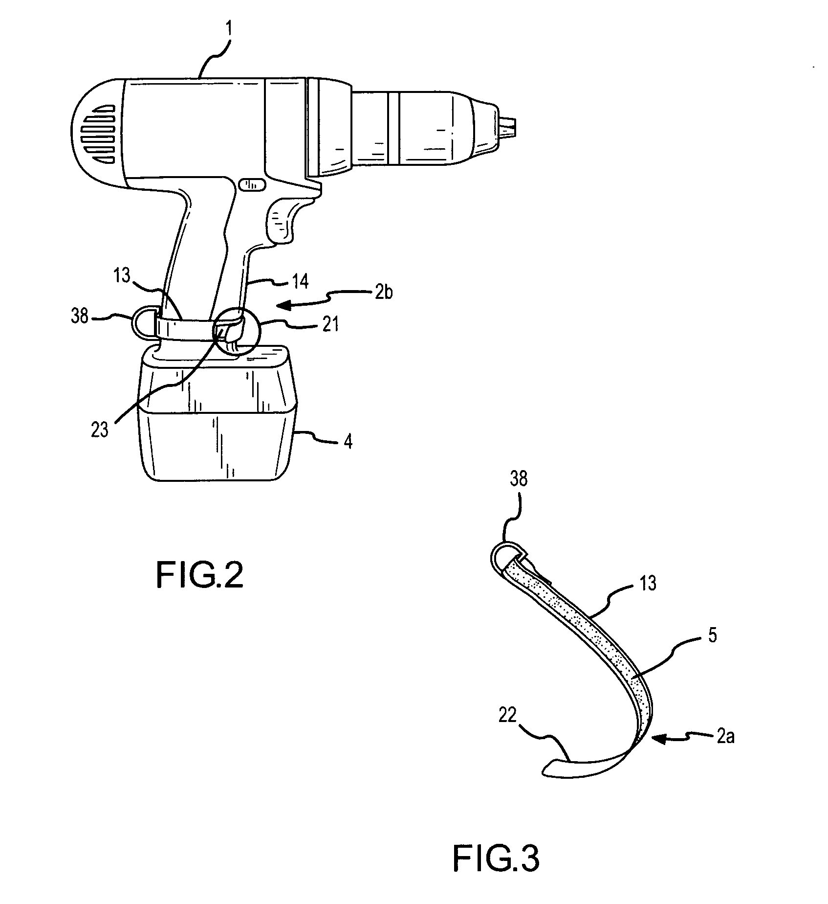
[0050] Now referring primarily to FIG. 1, a particular method of using the tool containment system includes the steps of providing a flexible member (13) which can operate between a planar condition (2a)(including the non-limiting examples of the flexible member (13) shown in FIGS. 3, 6, 8, 9, 12,14, 16, 18, 19, 23, and 25) and a conformed condition (2b)(including the non-limiting examples shown in FIGS. 1, 2, 4, 5, 7, 10, 11, 13, 15, 20, 21, and 22). By engaging a part of the external surface of a tool (1) with a part of a first flexible member surface (5) of the flexible member (13) in the planar condition (2a) the step of conforming the flexible member (13) to annularly engage a part of the external surface o...


PUM


Abstract

A tool containment system provides various configurations of a flexible member each of which can engage a part of the external surface of a tool to provide connection means for a tether to limit travel of the tool, or to oppose disassembly of tool components, or both.

Description

[0001] This United States Patent Application claims the benefit of U.S. Provisional Patent Application No. 60 / 738,479, filed Nov. 21, 2005, hereby incorporated by reference herein. I. BACKGROUND [0002] A tool containment system provides various configurations of a flexible member each of which can engage a part of the external surface of a tool to provide connection means for a tether to limit travel of the tool, or to oppose disassembly of tool components, or both. [0003] There exists a large commercial market for tools that can aid a person in accomplishing a task. Manufacturers have met the demand in that commercial market with a wide variety of hand tools which over time have evolved into power tools using motors powered by conventional line current or by rechargeable battery supplies which can uncouple from the various tools for recharging. While power tools may be convenient to use, especially cordless power tools using rechargeable battery supplies, there remain substantial u...

Claims


Application Information

Patent Timeline
Patent Type & Authority Applications(United States)
IPC IPC(8): B65D81/24
CPCB25H3/006Y10S224/904
Inventor MIKESELL, KENNETH W.BIBLE, MICHAEL J.
Owner CASTLE MOUNTAIN ENTERPRISES
Why Eureka
Try Eureka