Ultrasound sensor

a technology of ultrasound sensor and ultrasound tube, which is applied in the field of ultrasound sensor, can solve the problems of restricted irregular and difficulty in providing housing with optimal characteristic for transferring ultrasound, so as to reduce vibration region of vehicle periphery, the effect of increasing the amount of ultrasound transfer and restricting the directivity of ultrasound sensor

Inactive Publication Date: 2007-05-24
DENSO CORP
View PDF5 Cites 33 Cited by
  • Summary
  • Abstract
  • Description
  • Claims
  • Application Information

AI Technical Summary

Benefits of technology

[0011] Because the end portion of the housing is provided with the ultrasound transferring member having the acoustic impedance which can be predetermined set, the ultrasound reflection amount between the ultrasound vibrator and the ultrasound transferring member and the ultrasound reflection amount between the ultrasound transferring member and the vehicle periphery member can be reduced. Therefore, the ultrasound transfer amount can be increased.
[0012] Generally, because the stiffness and the like of the housing are to be maintained for a fixing of the ultrasound vibrator and for a mounting of the hous

Problems solved by technology

Generally, because the stiffness and the like of the housing are to be maintained for a fixing of the ultrasound vibrator and for a mounting of the housing to the vehicle periphery member, it is greatly difficult to

Method used


Image

  • Ultrasound sensor
  • Ultrasound sensor
  • Ultrasound sensor

Examples


first embodiment

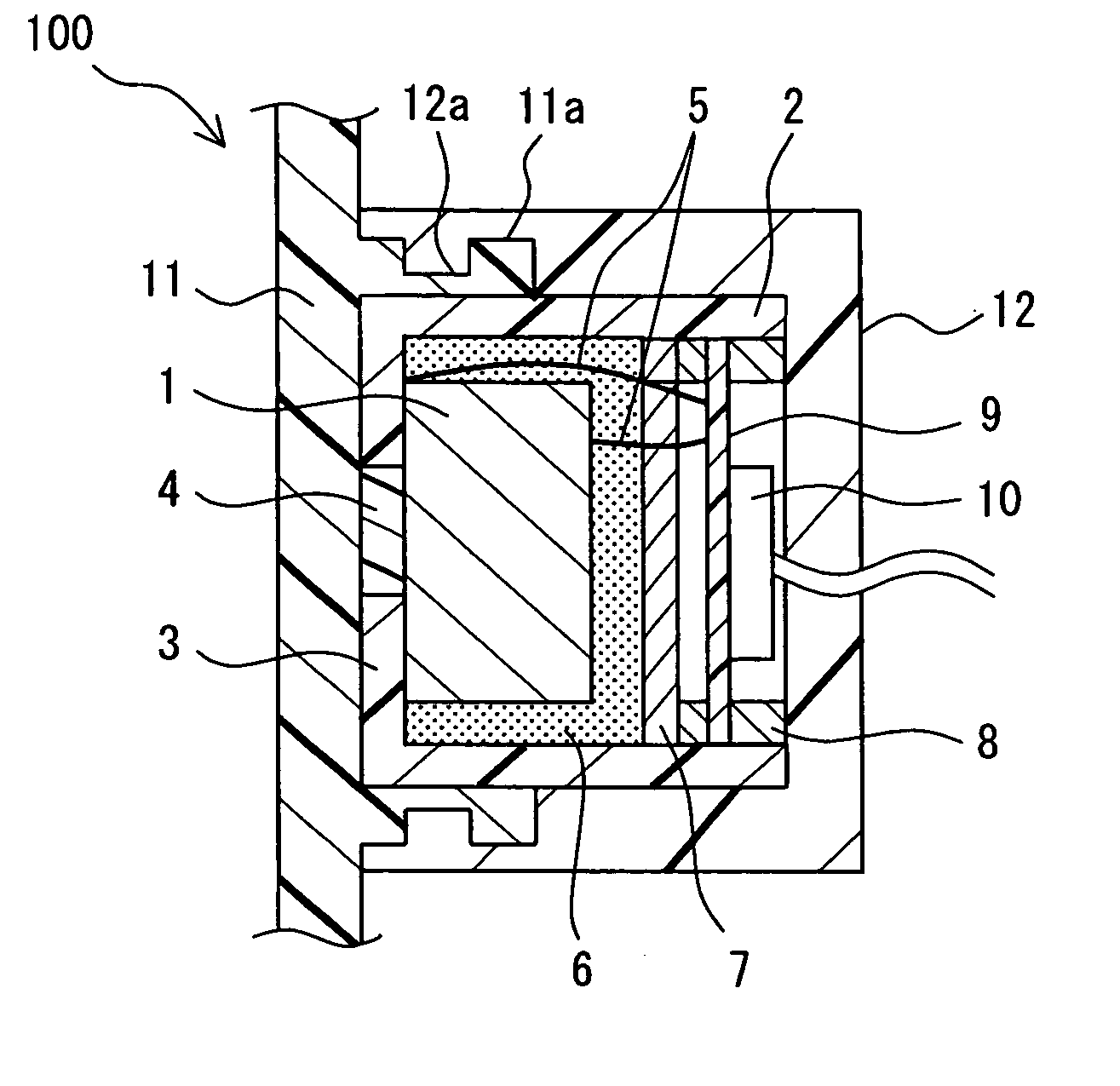
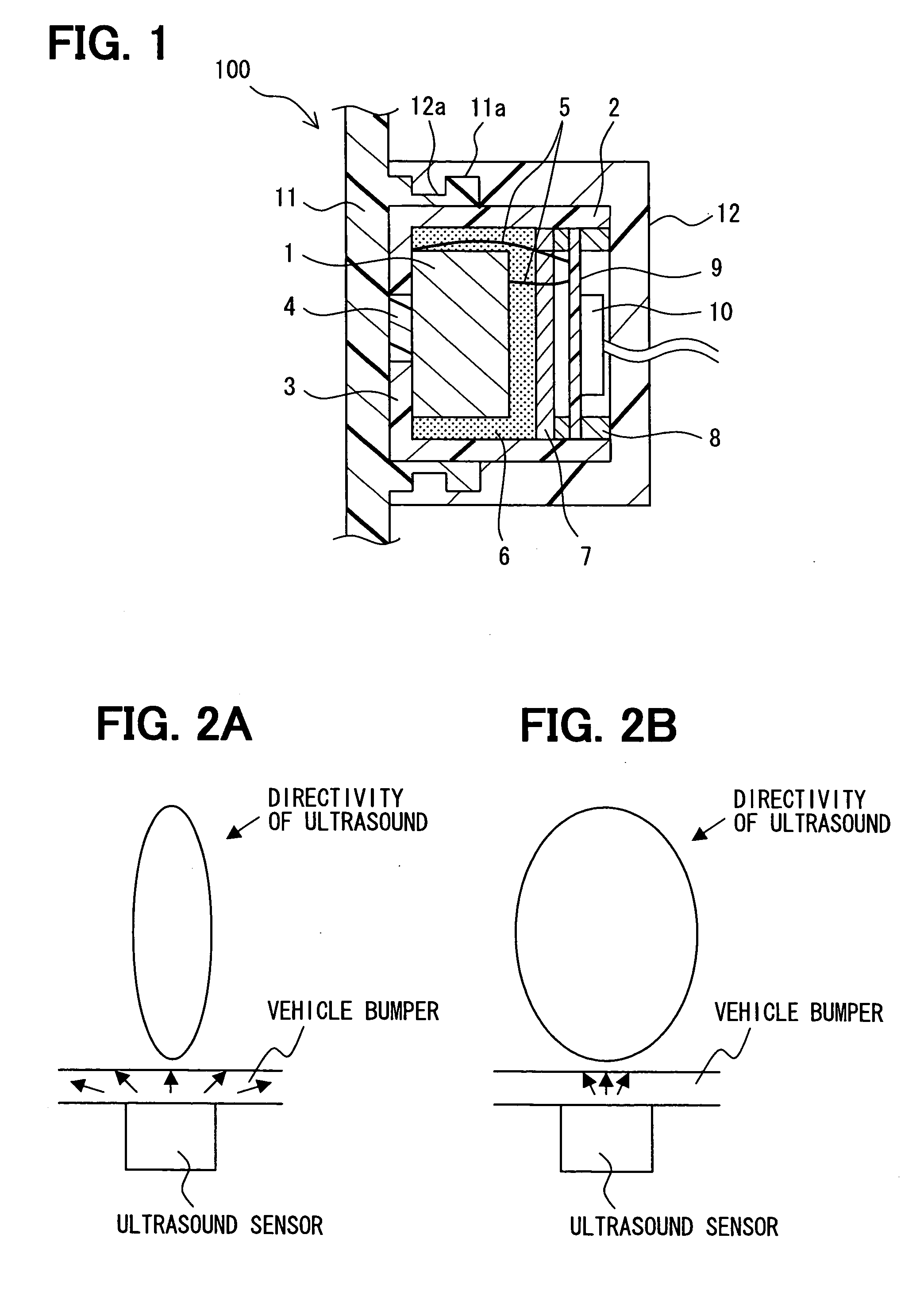
[0018] An ultrasound sensor 100 according to a first embodiment of the present invention will be described with reference to FIGS. 1 and 2B. The ultrasound sensor 100 can be suitably used in an obstacle detection device for detecting an obstacle around a vehicle or the like. In this case, the ultrasound sensors 100 can be mounted to an inner surface (i.e., surface of inner side of vehicle) of a periphery member (e.g., bumper 11) of the vehicle. For example, the ultrasound sensors 100 can be positioned at four corners of the vehicle.

[0019]FIG. 1 shows the ultrasound sensor 100 which is attached to the vehicle to contact the back surface (i.e., inner surface) of the bumper 11. The ultrasound sensor 100 has an ultrasound vibrator 1 (e.g., piezoelectric vibrator), an ultrasound transferring member 4, a circuit board 9 where a processing circuit is arranged, and a housing 2 which houses therein the piezoelectric vibrator 1 and the circuit board 9 and the like. The housing 2 is fixed to ...

second embodiment

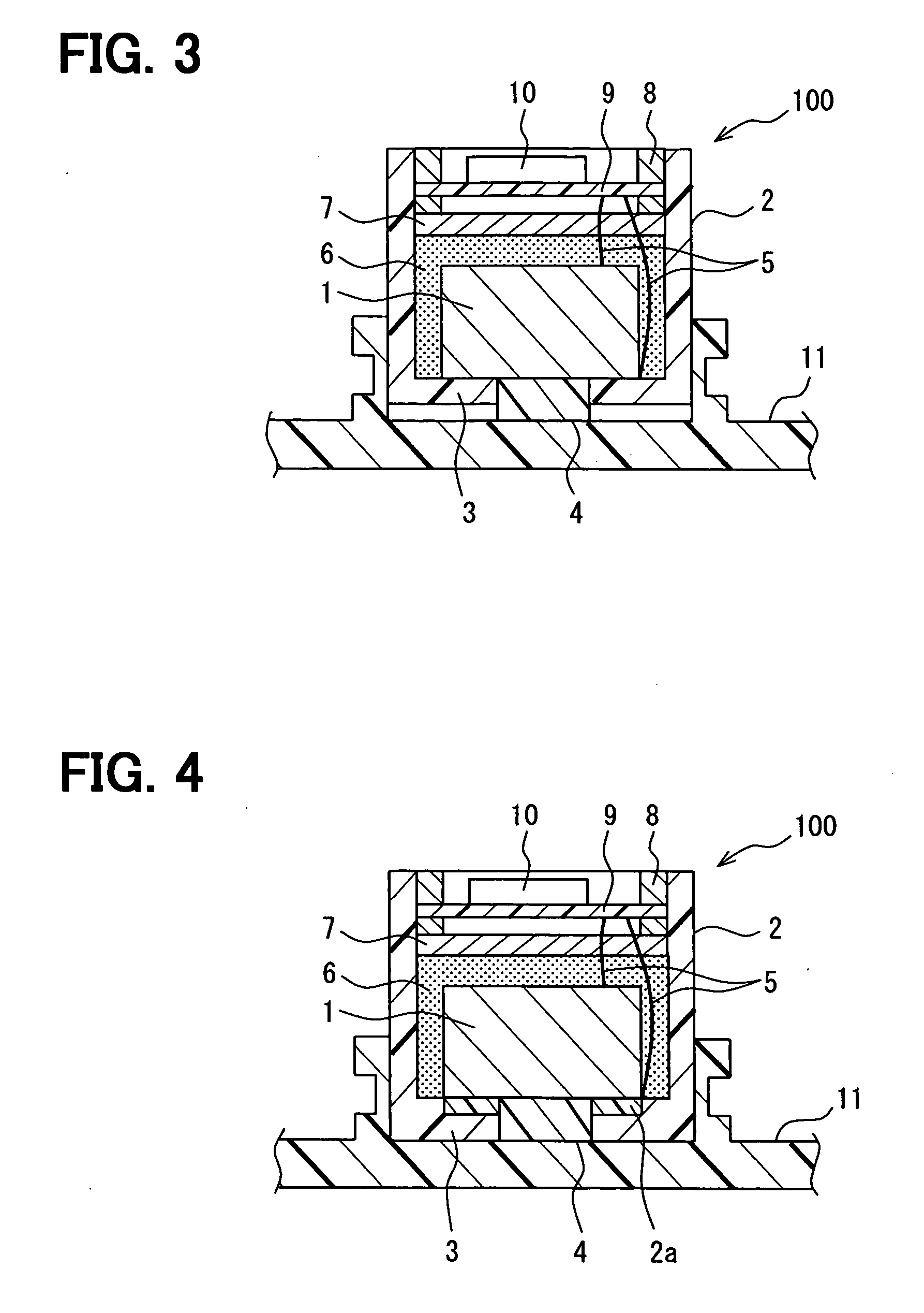
[0048] According to a second embodiment of the present invention, as shown in FIG. 3, the ultrasound transferring member 4 has a larger thickness than the bottom 3 of the housing 2. In this case, the ultrasound transferring member 4 protrudes toward the side of the bumper 11 from the bottom 3 to contact the inner surface of the bumper 11, and is arranged at the substantially same plane with the bottom 3 at the side of the piezoelectric vibrator 1. That is, the piezoelectric vibrator 1 contacts both the ultrasound transferring member 4 and the bottom 3. The bottom 3 is constructed of the same material with the housing 2 and positioned around the ultrasound transferring member 4.

[0049] In this embodiment, a gap is arranged between the outer surface of the bottom 3 of the housing 2 and the bumper 11. That is, an end surface of the ultrasound transferring member 4 is positioned at the further outer side (with respect to inner side of housing 2) than the outer surface of the bottom 3.

[...

third embodiment

[0052] According to a third embodiment of the present invention, as shown in FIG. 4, the ultrasound transferring member 4 has a larger thickness than the bottom 3 of the housing 2. The ultrasound transferring member 4 protrudes toward the side of piezoelectric vibrator 1 from the bottom 3, and is arranged at the substantially same plane with the bottom 3 at the side of the bumper 11. That is, the bumper 11 contacts both the ultrasound transferring member 4 and the bottom 3. The bottom 3 is constructed of the same material with the housing 2 and positioned around the ultrasound transferring member 4, for example.

[0053] In this embodiment, the piezoelectric vibrator 1 is isolated from the bottom 3 of the housing 2, by an ultrasound attenuating portion 2a which is made of a material having an ultrasound attenuation coefficient larger than that of the material of the housing 2. For example, the ultrasound attenuating portion 2a can be made of a rubber, or an elastomer or the like which...


PUM


Abstract

An ultrasound sensor for a vehicle has a housing which is fixedly arranged at a vehicle inner side of a periphery member of the vehicle, an ultrasound vibrator for sending and receiving ultrasound, and an ultrasound transferring member which is constructed of a different material from that of the housing to have an acoustic impedance with a medium value between an acoustic impedance of the ultrasound vibrator and that of the periphery member. The ultrasound vibrator is accommodated in the housing and fixed to an end portion of the housing, which faces the periphery member. The ultrasound transferring member is arranged at the end portion of the housing, and contacts both the ultrasound vibrator and the periphery member of the vehicle.

Description

CROSS REFERENCE TO RELATED APPLICATION [0001] This application is based on a Japanese Patent Application No. 2005-336127 filed on Nov. 21, 2005, the disclosure of which is incorporated herein by reference. FIELD OF THE INVENTION [0002] The present invention relates to an ultrasound sensor, which can be suitably used for a vehicle, for example. BACKGROUND OF THE INVENTION [0003] A vehicle can be provided with an ultrasound sensor for detecting an obstacle around the vehicle. For example, as disclosed in JP-2004-264264A, a bumper of the vehicle is provided with a hole, through which the head portion of the ultrasound sensor is exposed to the exterior in such a manner that the outer surface of the head portion is arranged at the same surface with the outer surface of the bumper. In this case, the appearance of the vehicle is impaired because the head portion of the ultrasound sensor is exposed to the exterior of the vehicle. [0004] In order to solve this problem, as disclosed in JP-10-...

Claims


Application Information

Patent Timeline
IPC IPC(8): B60Q1/00G01S15/931
CPCG01S7/521G01S15/931G10K9/122G01S2015/938
Inventor NAKANO, AKIOTSUZUKI, TAKEOSATO, YOSHIHISAKOJIMA, KIYONARI
Owner DENSO CORP
Why Eureka
Try Eureka