Power supply with low standby loss

a power supply and low standby loss technology, applied in the direction of electric variable regulation, process and machine control, instruments, etc., can solve the problems of only applicable methods of reducing switching frequency, large ripple wave of output voltage in standby mode, and audio noise, etc., to achieve low standby loss and high standby loss

Active Publication Date: 2007-05-24
DELTA ELECTRONICS INC
View PDF9 Cites 47 Cited by
  • Summary
  • Abstract
  • Description
  • Claims
  • Application Information

AI Technical Summary

Benefits of technology

[0009] In view of the drawbacks of prior art, switch mode power having high standby loss, the present invention provides a power supply with low standby loss that a main power converter connects parallelly with an auxiliary power converter.

Problems solved by technology

However, if this method is deployed to save energy, audio-noise will appear when the switching frequency is lowered to 20 KHz or below.
Thus, some manufacturers developing this type of energy-saving control chips have to deploy frequency jolting and peak current limitation techniques to weaken or reduce noise signals.
In addition, the method of reducing the switching frequency is only applicable to a pulse width modulation (PWM) converter.
However, the ripple wave of the output voltage in the standby mode is considerably large and acoustic frequency noise signal is more likely to appear.
Although all the aforementioned methods can reduce power loss in the standby mode, they can hardly meet some of the more stringent requirements for reducing power loss in switching mode power sources with a larger output power.
Therefore, the switching loss and the driving loss of the circuits will be enormously increased owing to increasingly number of semiconductor switching devices and specifications of voltage and current of the semiconductor switching devices.
Moreover, control circuits had varied more complicated accompanying with complicated circuits to need more power consumption.

Method used


Image

  • Power supply with low standby loss
  • Power supply with low standby loss
  • Power supply with low standby loss

Examples


Embodiment Construction

[0029] In the following description, numerous specific details are set forth in order to provide a thorough understanding of the present invention, and the scope of the present invention is expressly not limited expect as specified in the accompanying claims. One skilled in the relevant art will recognize, however, that the invention may be practiced without one or more of the specific details. In other instances, well known structures, materials, or operations are not shown or described in order to avoid obscuring aspects of the invention.

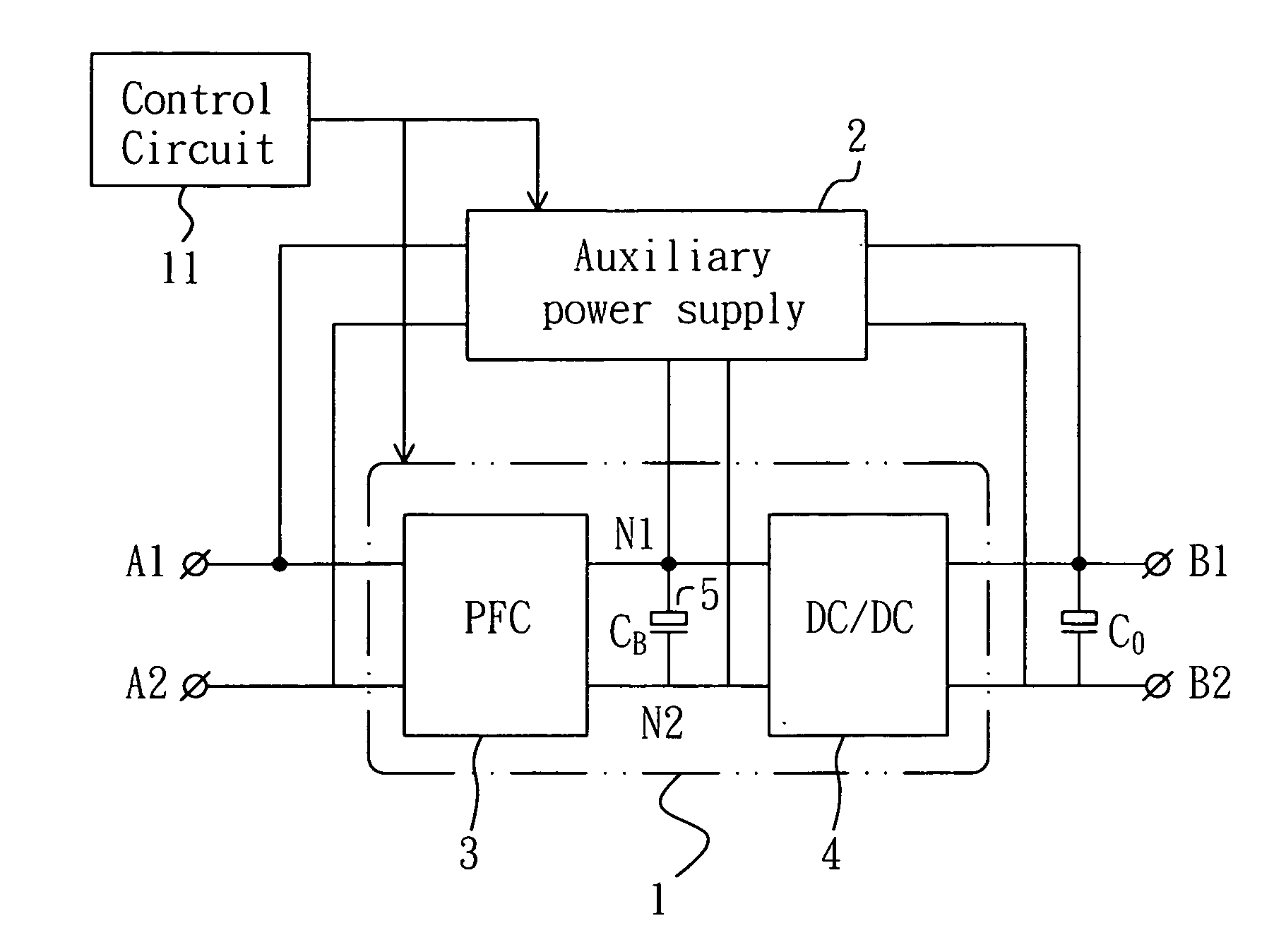
[0030] Those of ordinary skill in the art will immediately realize that the embodiments of the present invention described herein in the context of methods and schematics are illustrative only and are not intended to be in any way limiting. Other embodiments of the present invention will readily suggest themselves to such skilled persons having the benefits of this disclosure. FIG. 1 shows a converter topology of power supply with low standby los...


PUM


Abstract

The present invention discloses a power supply device with low standby loss. The power supply device comprises a main power converter and an auxiliary power converter. The main power converter comprises a bulk capacitor. The main power converter connects parallelly with the auxiliary power converter. When the power supply device is in a standby mode, the main converter is turned off and the auxiliary converter provides the output to the outputting load and the bulk capacitor. Moreover, when the power supply device is in a normal mode, the main converter and the auxiliary converter together provide the output to an outputting load. Under a normal mode, the main converter provides most of the power and the auxiliary converter operates in a power-limited finite value such that the topology of the power supply device achieves a low standby loss.

Description

BACKGROUND OF THE INVENTION [0001] 1. Field of the Invention [0002] The present invention relates to a switching mode power supply, and more particularly, the present invention relates to the power supply with low standby loss and a main power converter connected parallelly with an auxiliary power converter of the power supply. [0003] 2. Description of the Related Art [0004] In the design of a switching mode power source, a system requires high switching efficiency, high power density, high reliability, low production cost and quick dynamic response to a loading. With the worldwide campaign for saving energy, all switching mode power sources are demanded to have low standby power wastage. In this regard, various international organizations including the International Energy Association (IEA), the United States and many European countries have proposed or are planning a set of related standards to limit the power consumed by an electronic product using a switching mode power source i...

Claims


Application Information

Patent Timeline
Patent Type & Authority Applications(United States)
IPC IPC(8): H02M3/335
CPCH02M3/1582H02M2001/0032Y02B70/16H02M1/0032Y02B70/10
Inventor LOU, JUNSHANFENG, JIANGTAOGAN, HONGJIAN
Owner DELTA ELECTRONICS INC
Why Eureka
Try Eureka