Energy efficient power supply device and operating method thereof

a power supply device and energy-saving technology, applied in the direction of electric variable regulation, process and machine control, instruments, etc., can solve the problems of only applicable methods of reducing switching frequency, large ripple wave of output voltage in standby mode, and high noise appearance of audio, so as to achieve low standby loss and high switching efficiency

Active Publication Date: 2007-02-06
DELTA ELECTRONICS INC
View PDF3 Cites 13 Cited by
  • Summary
  • Abstract
  • Description
  • Claims
  • Application Information

AI Technical Summary

Benefits of technology

[0012]Accordingly, at least one objective of the present invention is to provide a power supply device having a main converter and an auxiliary converter connected in parallel to form an output topological structure for providing output power. Under a normal load, the main converter provides most of the power and the auxiliary converter operates in a power-limited mode (that is, the output power is less than a fixed value). In the standby mode, the main converter is shut down so that output power to the load is provided solely through the auxiliary converter. In the meantime, the output dynamic response of the main converter is maintained through a power factor corrector (PFC) and a first capacitor. Therefore, high switching efficiency and low standby loss are achieved.
[0020]In the present invention, a main / auxiliary converter output parallel connected topological structure is deployed so that the main and the auxiliary converter can provide the output power together. Thus, under a normal loading, most of the power is supplied by the main converter while the auxiliary converter operates in a power-limited mode (the output power is always below a fixed value). In the standby mode, the output power is entirely supplied by the auxiliary converter so that the main converter is no longer in operation. Therefore, a high switching efficiency and low standby energy consumption can be achieved at the same time. Furthermore, because the capacitor is disposed in parallel between the power factor corrector and the DC / DC converter, the voltage at the first capacitor can be maintained through the power factor corrector in the standby mode to satisfy the output dynamic response of the main converter.

Problems solved by technology

However, if this method is deployed to save energy, audio-noise will appear when the switching frequency is lowered to 20 KHz or below.
Thus, some manufacturers developing this type of energy-saving control chips have to deploy frequency jolting and peak current limitation techniques to weaken or reduce noise signals.
In addition, the method of reducing the switching frequency is only applicable to a pulse width modulation (PWM) converter.
However, the ripple wave of the output voltage in the standby mode is considerably large and acoustic frequency noise signal is more likely to appear.
Although all the aforementioned methods can reduce power loss in the standby mode, they can hardly meet some of the more stringent requirements for reducing power loss in switching mode power sources with a larger output power.

Method used


Image

  • Energy efficient power supply device and operating method thereof
  • Energy efficient power supply device and operating method thereof
  • Energy efficient power supply device and operating method thereof

Examples


Embodiment Construction

[0030]Reference will now be made in detail to the present preferred embodiments of the invention, examples of which are illustrated in the accompanying drawings. Wherever possible, the same reference numbers are used in the drawings and the description to refer to the same or like parts.

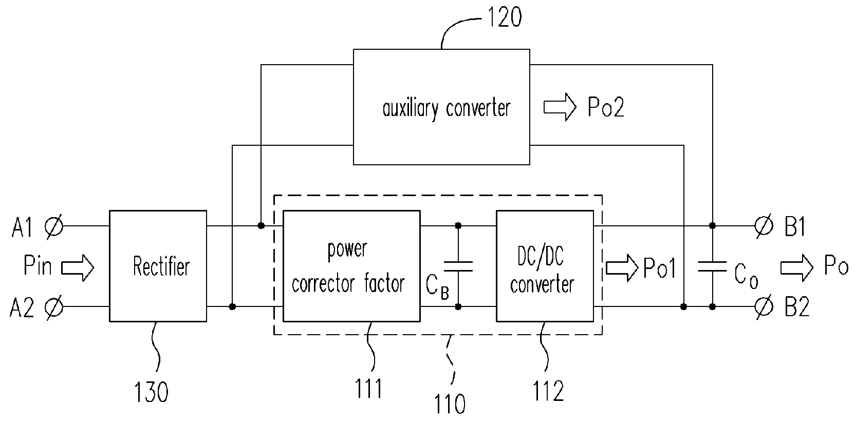
[0031]FIG. 1 is a block diagram showing a main / auxiliary converter output parallel connected topological structure according to one preferred embodiment of the present invention. As shown in FIG. 1, the main converter 110 and the auxiliary converter 120 are connected in parallel at points A1, A2 and B1, B2. Furthermore, the input power Pin picked up at points A1, A2 are rectified by a rectifier 130 before distributing to the main converter 110 and the auxiliary converter 120. The points A1, A2 represent the input terminals of the switching mode power source. Typically, the points A1 and A2 are connected to an alternating current power source. The points B1, B2 represent the output terminals of the sw...


PUM


Abstract

A power supply device and an operating method thereof are provided. The power supply device includes a main converter and an auxiliary converter. The main converter includes a power factor corrector (PFC), a first capacitor that connects in parallel with the PFC and a DC / DC converter that connects in parallel with the first capacitor. The auxiliary converter is connected in parallel to the main converter. When the power supply device operates in a normal mode, the main converter and the auxiliary converter together provide a first output to an output load. When the power supply device is in a standby mode, the DC / DC converter is turned off so that only the auxiliary converter provides a second output to the output load. Meanwhile, the PFC is in operation to maintain the voltage of the first capacitor in order to meet the demand of the output dynamic response of the main converter.

Description

CROSS-REFERENCE TO RELATED APPLICATION[0001]This application claims the priority benefit of Taiwan application Ser. No. 93,137,339, filed on Dec. 3, 2004. All disclosure of the Taiwan application is incorporated herein by reference.BACKGROUND OF THE INVENTION[0002]1. Field of the Invention[0003]The present invention relates to a power supply device and an operating method thereof. More particularly, the present invention relates to the topological structure and operating method of an energy efficient switching mode power supply device.[0004]2. Description of the Related Art[0005]In the design of a switching mode power source, a system requires high switching efficiency, high power density, high reliability, low production cost and quick dynamic response to a loading. With the worldwide campaign for saving energy, all switching mode power sources are demanded to have low standby power wastage. In this regard, various international organizations including the International Energy Asso...

Claims


Application Information

Patent Timeline
Patent Type & Authority Patents(United States)
IPC IPC(8): H02M7/23
CPCH02M3/285Y02B70/16H02M2001/0032H02M1/0032Y02B70/10
Inventor LIN, KUN-CHIZHANG, YOUJUNKONG, QINGGANGLOU, JUNSHANGAN, HONGJIAN
Owner DELTA ELECTRONICS INC
Why Eureka
Try Eureka