System and method for testing a vehicle suspension

Inactive Publication Date: 2007-05-24
FORD MOTOR CO
View PDF8 Cites 31 Cited by
  • Summary
  • Abstract
  • Description
  • Claims
  • Application Information

AI Technical Summary

Benefits of technology

[0009] According to one embodiment of the present invention, a computer system for testing a vehicle suspension using a kinematics rig having one or more rig feedback sensors is disclosed. The computer system includes a central processing unit (CPU) for executing machine instructions; a memory for storing machine instructions that are to be executed by the CPU; and a rig control circuit in electrical communication with the CPU for operating the kinematics rig and the one or more rig feedback sensors. The machine instructions when executed by the CPU implement the following functions: receiving an input corresponding to a pre-programmed test procedure for testing the vehicle suspension; transmitting a control signal to the kinematics rig corresponding to the test procedure; receiving suspension data sensed by one or more vehicle suspension sensors during execution of the test procedure; receiving rig data sensed by the one or more rig feedback sensors during execution of the test procedure; and formatting the suspension data and rig data for display via a graphical user interface (GUI).
[0010] According to another embodiment of the present invention, a computer system for testing a vehicle suspension using a kinematics rig having one or more rams for supporting the vehicle at its wheels and having one or more rig feedback sensors is disclosed. The computer system includes a central processing unit (CPU) for executing machine instructions; a memory for storing machine instructions that are to be executed by the CPU; and a rig control circuit in electrical communication with the CPU for operating the kinematics rig. The machine instructions when executed by the CPU implemen

Problems solved by technology

Ride and handling, in particular, may be greatly impacted by the vehicle's suspension.
Because of the high speeds racecars travel, steering control is critically important, but it is also quite volatile.
Even the slightest change in the condition of the vehicle or track can significantly alter the ride and handling, and thus, the steering control of the racecar.
Accordingly, race teams may invest a lot of time and expense in testing the performance of a vehicle's suspension.
Current kine

Method used


Image

  • System and method for testing a vehicle suspension
  • System and method for testing a vehicle suspension
  • System and method for testing a vehicle suspension

Examples


Embodiment Construction

)

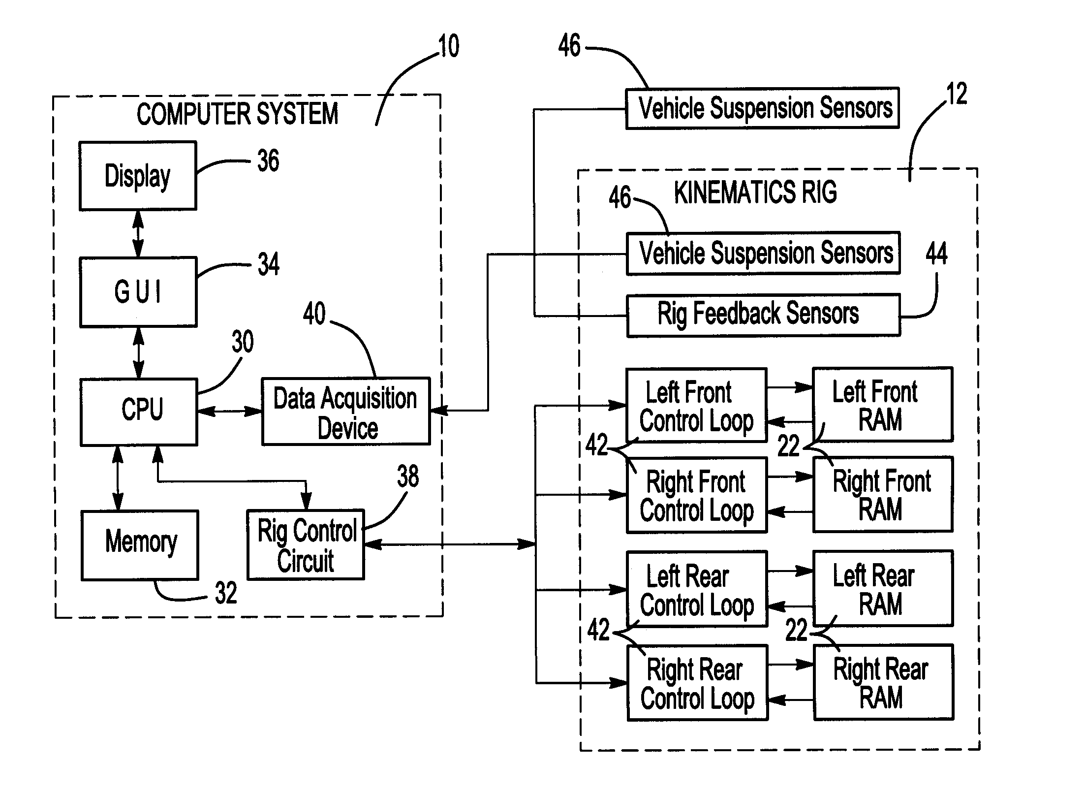
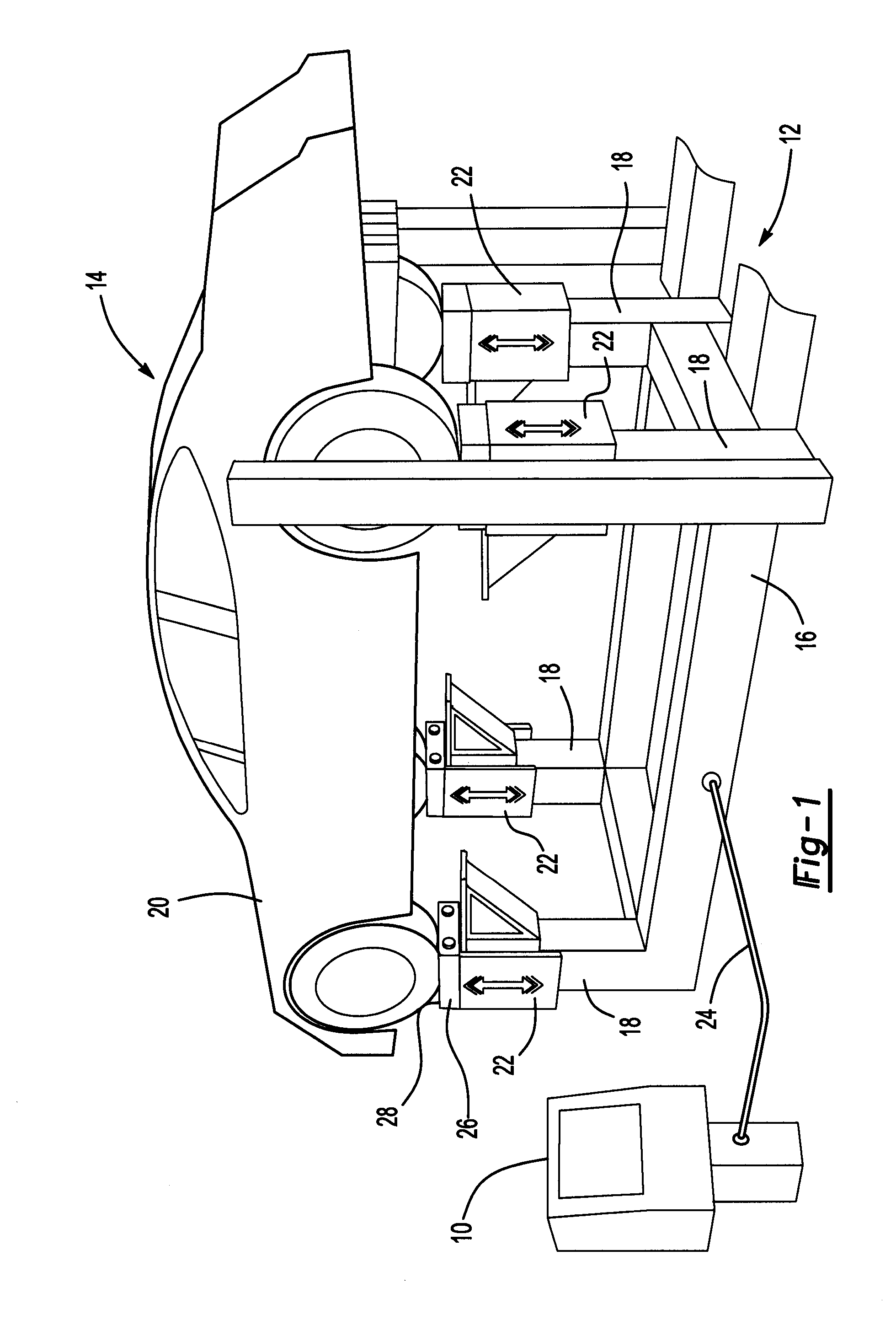
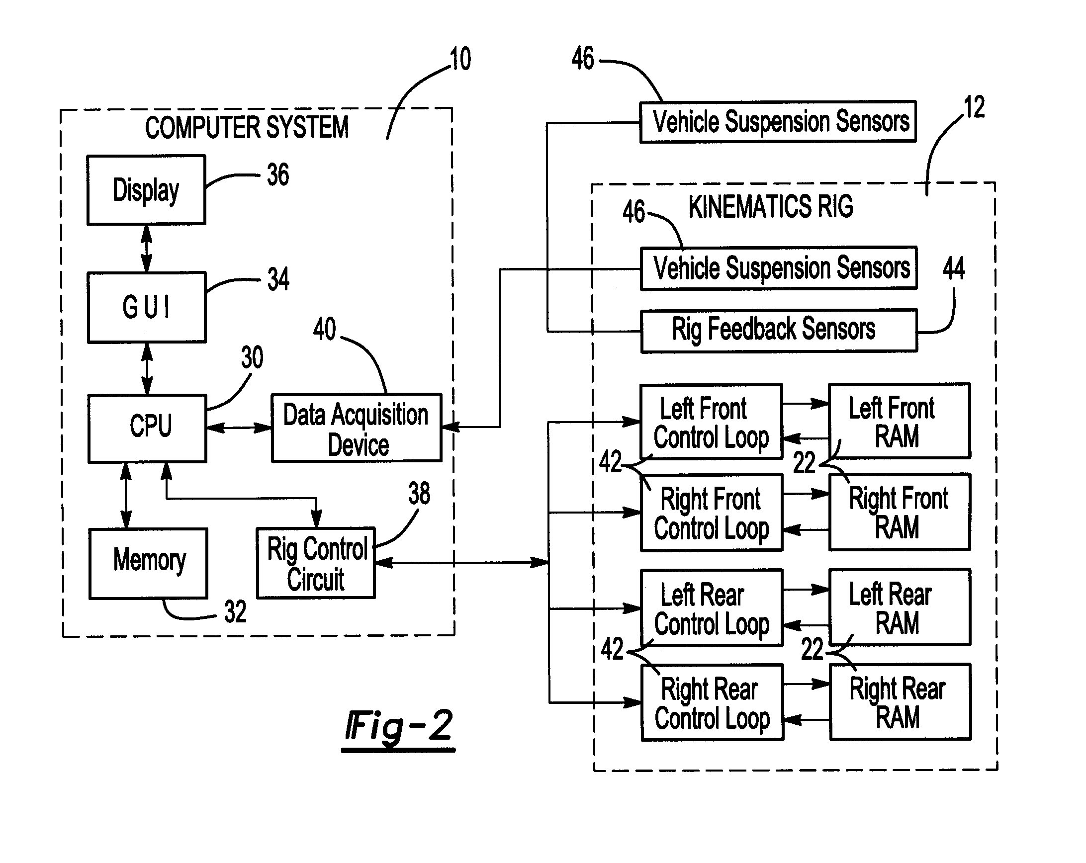
[0022]FIG. 1 shows a computer system 10 and a kinematics rig 12 of a vehicle suspension test system 14 according to one embodiment of the present invention. The computer system 10 provides the interface between the kinematics rig 12 and an operator, e.g., a test engineer. As depicted in FIG. 1, the kinematics rig 12 is a full vehicle kinematics rig, although other kinematics rigs can be used in accordance with this invention. The kinematics rig 12 can be manufactured in various ways as is known in the art and mainly consists of a rigid base 16 for supporting four vertical posts 18, which in turn support the four wheels of a loaded test vehicle 20.

[0023] Each vertical post 18 of the kinematics rig 12 can be equipped with an independently controlled ram 22 that can be displaced linearly permitting vertical deflection of the vehicle's wheel. The rams 22 can be actuated by any means known in the art, for example, by hydraulic control, pneumatic control, or the like, without departing ...


PUM


Abstract

According to one embodiment of the present invention a method for testing a vehicle suspension using a kinematics rig is disclosed. The method includes receiving an input corresponding to a pre-programmed test procedure for testing the vehicle suspension; transmitting a control signal to the kinematics rig corresponding to the test procedure; receiving suspension data sensed by one or more vehicle suspension sensors during execution of the test procedure; receiving rig data sensed by one or more rig feedback sensors during execution of the test procedure; and formatting the suspension data and rig data for display via a graphical user interface (GUI).

Description

CROSS-REFERENCE TO RELATED APPLICATIONS [0001] This application claims the benefit of U.S. Provisional Application Ser. No. 60 / 738,232 filed Nov. 18, 2005.BACKGROUND OF THE INVENTION [0002] 1. Field of the Invention [0003] One embodiment of the present invention relates to a system and method for testing a vehicle suspension. [0004] 2. Background Art [0005] Overall vehicle performance can be influenced by several factors. Typical factors may include characteristics of the engine, drivetrain, chassis, vehicle durability, and ride and handling. Ride and handling, in particular, may be greatly impacted by the vehicle's suspension. A suspension typically includes a system of springs, shock absorbers and linkages that connects a vehicle to its wheels. To this end, testing the suspension of a vehicle can provide essential information regarding the ride and handling of a vehicle. Testing a vehicle's suspension can also aid in predicting the suspension's performance. For example, analyzing ...

Claims


Application Information

Patent Timeline
IPC IPC(8): G06F19/00
CPCG01M17/04
Inventor PROBST, JOHNSATCHELL, TERRY
Owner FORD MOTOR CO
Why Eureka
Try Eureka