Swing hinge device for portable terminal and portable terminal having the same

a technology of swinging hinge and portable terminal, which is applied in the field of portable terminals, can solve the problems of limiting the thickness of the portable terminal, inconvenient to carry the portable terminal, and early mobile communication services using the portable terminal were limited, so as to improve the portability of the portable terminal and reduce the size of the portable terminal

Inactive Publication Date: 2007-05-31
SAMSUNG ELECTRONICS CO LTD
View PDF19 Cites 19 Cited by
  • Summary
  • Abstract
  • Description
  • Claims
  • Application Information

AI Technical Summary

Benefits of technology

[0015] An aspect of the present invention is to address at least the above problems and / or disadvantages and to provide at least the advantages described below. Accordingly, an aspect of the present invention is to provide a hinge device for a portable terminal which can contribute to the reduction is size of the portable terminal, thereby improving the portability of the portable terminal.

Problems solved by technology

Early mobile communication services using the portable terminal were limited to voice communication services, short message sending services, and the like.
A portable terminal having three housings has large dimensions or thickness as compared with its structure, so it is inconvenient to carry the portable terminal.
Furthermore, the structure of the conventional hinge device (that is, the guide plate and washer plate stacked between the first and second hinge bases and balls that are interposed between the second hinge base and the guide plate, as described above) limits the amount that the thickness of a portable terminal can be reduced.
Furthermore, since the conventional hinge device is produced by assembling a plurality of parts, manufacturing productivity is hindered.

Method used


Image

  • Swing hinge device for portable terminal and portable terminal having the same
  • Swing hinge device for portable terminal and portable terminal having the same
  • Swing hinge device for portable terminal and portable terminal having the same

Examples


Embodiment Construction

[0030] The matters defined in the description such as a detailed construction and elements are provided to assist in a comprehensive understanding of the exemplary embodiments of the invention. Accordingly, those of ordinary skill in the art will recognize that various changes and modifications of the exemplary embodiments described herein can be made without departing from the scope and spirit of the invention. Also, descriptions of well-known functions and constructions are omitted for clarity and conciseness.

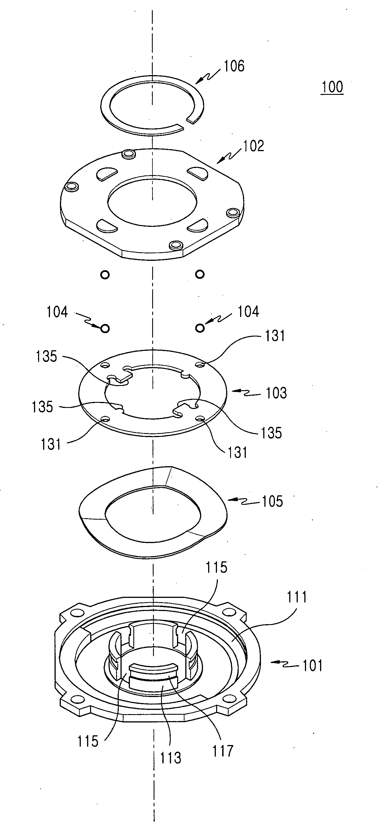
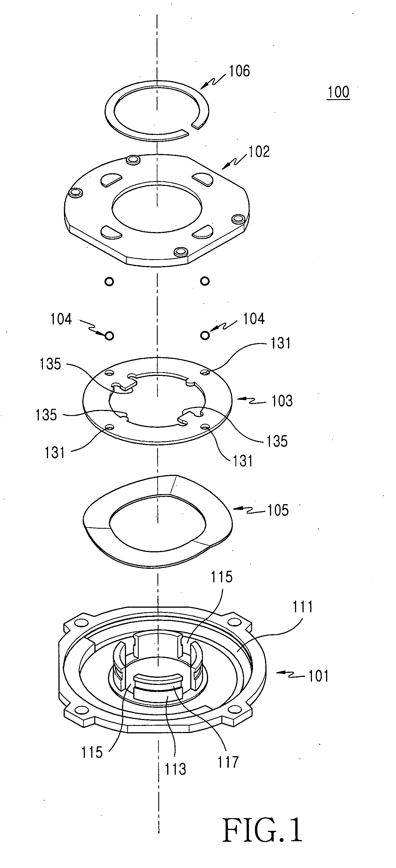
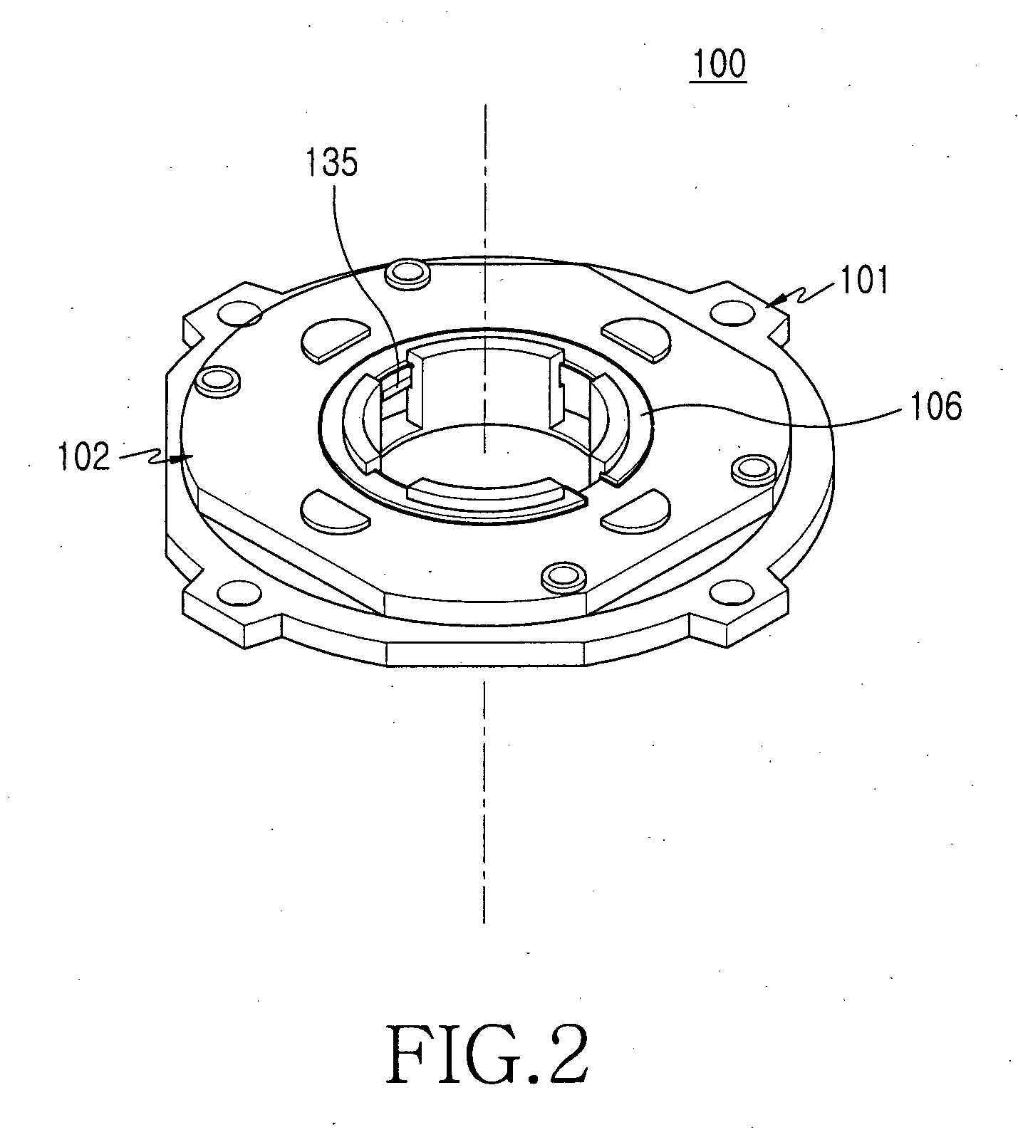
[0031] As shown in FIGS. 3 through 6, a hinge device 200 of a portable terminal, according to an exemplary embodiment of the present invention, is provided with first and second hinge bases 201 and 202 rotatably coupled to each other and facing each other. An elastic member 203 is disposed between the first and second hinge bases 201 and 202. The elastic member 203 is arranged around an exterior peripheral surface of a stopper rib 223 formed on the second hinge base 202. In ...


PUM


Abstract

A hinge device for a portable terminal includes a first hinge base, a second hinge base, and an elastic member. The first hinge base has a receiving groove on a surface thereof. The second hinge base is rotatably coupled to the first hinge base and has stopper ribs which extend from a surface of the second hinge base and are arranged along a circumferential direction. The elastic member is received in the receiving groove of the first hinge base and presses against an outer peripheral surface of the stopper ribs as the second hinge base rotates with respect to the first hinge base. The hinge device has a reduced number of parts so as to allow easy assembly of the hinge device, thereby improving manufacturing productivity. Further, the structure with the elastic member that presses the stopper rib minimizes the size of the portable terminal and improves the portability of the portable terminal.

Description

PRIORITY [0001] This application claims the benefit under 35 U.S.C. § 119(a) of an application entitled “Swing Hinge Device For Portable Terminal” filed with the Korean Intellectual Property Office on Nov. 30, 2005 and assigned Serial No. 2005-116007, the entire contents of which are hereby incorporated by reference. BACKGROUND OF THE INVENTION [0002] 1. Field of the Invention [0003] The present invention relates to a portable terminal. More particularly, the present invention relates to a hinge device for rotatably coupling one housing of a portable terminal to another housing of a portable terminal. [0004] 2. Description of the Related Art [0005] Generally, a portable terminal is a device for providing a wireless communication function between users, or between a user and a service provider through a mobile communication base station. A user can receive and use through the portable terminal various kinds of services, such as a voice communication service, a short message sending s...

Claims


Application Information

Patent Timeline
Patent Type & Authority Applications(United States)
IPC IPC(8): E05D11/08
CPCG06F1/1616G06F1/1622G06F1/1679G06F1/1681Y10T16/5403H04M1/0212H04M1/0227H04M1/0233G06F1/1686H04B1/38
Inventor KIM, JAE-WOOK
Owner SAMSUNG ELECTRONICS CO LTD
Why Eureka
Try Eureka