
Pulse tube cryogenic cooler

Active Publication Date: 2007-05-31
SUMITOMO HEAVY IND LTD
View PDF7 Cites 8 Cited by
  • Summary
  • Abstract
  • Description
  • Claims
  • Application Information

AI Technical Summary

Benefits of technology

[0025] Accordingly, embodiments of the present invention may provide a novel and useful pulse tube cryogenic cooler, in which one or more of the problems described above are eliminated.
[0026] More specifically, the embodiments of the present invention may provide a pulse tube cryogenic cooler wherein a heat exchanging property of a heat exchanger is improved.
[0036] According to the above-mentioned pulse tube cryogenic cooler of the embodiments of the present invention, it is possible to improve the heat exchanging property of a heat exchanger and therefore a cooling property of the pulse tube cryogenic cooler can be improved.

Problems solved by technology

However, this heat exchanging cannot be made well due to the same reason as discussed above.

Method used


Image

  • Pulse tube cryogenic cooler
  • Pulse tube cryogenic cooler
  • Pulse tube cryogenic cooler

Examples


Embodiment Construction

[0044] A description will now be given, with reference to FIG. 3 through FIG. 6, of embodiments of the present invention.

[0045]FIG. 3 and FIG. 4 show pulse tube cryogenic coolers 20A and 20B of an embodiment of the present invention. More specifically, FIG. 3 is a structural view of a two-stage double inlet type pulse tube cryogenic cooler 20A of an embodiment of the present invention. FIG. 4 is a structural view of a two-stage four-valve type pulse tube cryogenic cooler 20B of an embodiment of the present invention.

[0046] First, the two-stage double inlet type pulse tube cryogenic cooler 20A of the embodiment of the present invention is discussed with reference to FIG. 3.

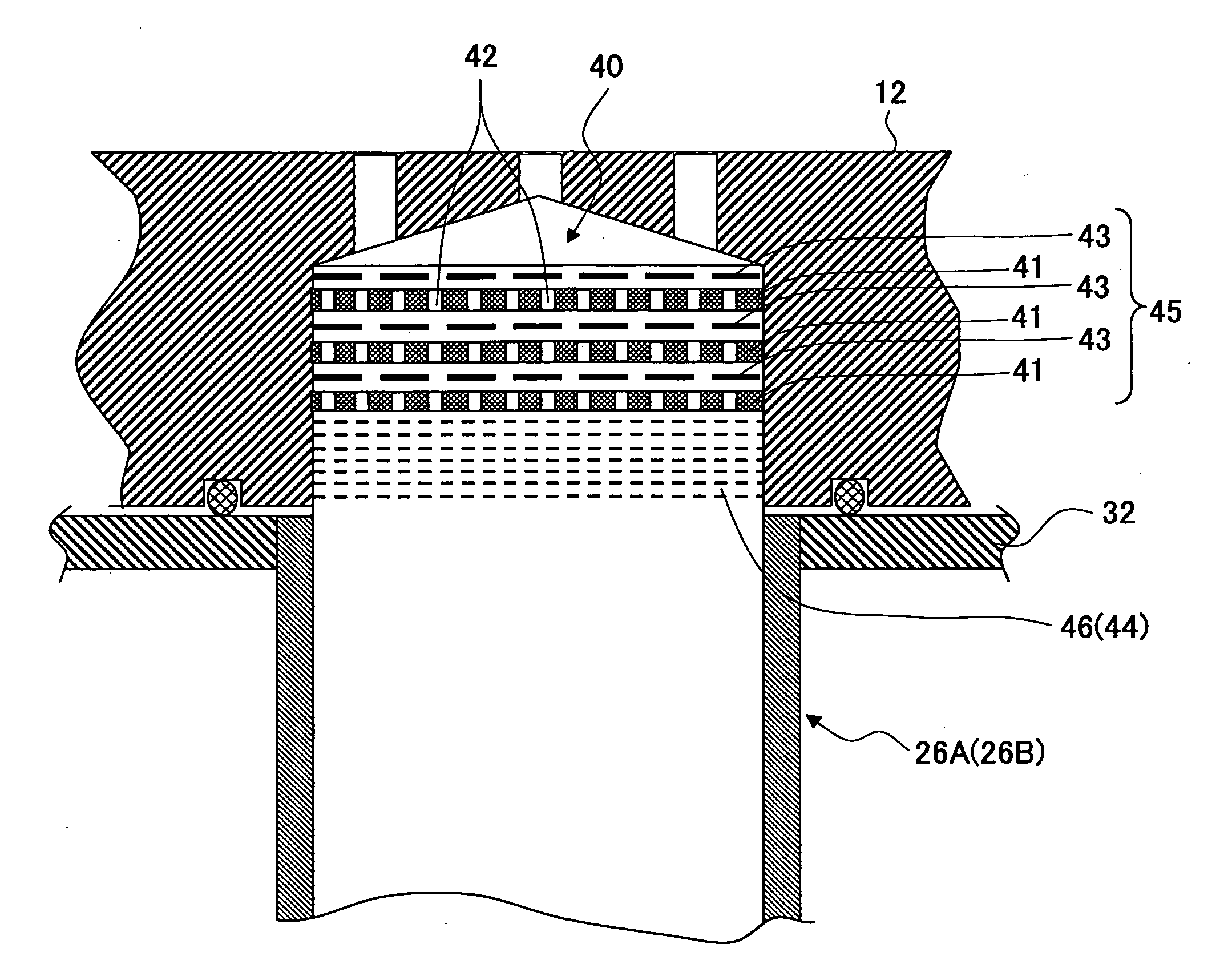
[0047] The pulse tube cryogenic cooler 20A is a two-stage type and therefore has a first step regenerator 22A and a second step regenerator 22B as regenerators. In addition, the pulse tube cryogenic cooler 20A has a first step pulse tube 26A and a second step pulse tube 26B as pulse tubes.

[0048] A high temperat...


PUM


Abstract

A pulse tube cryogenic cooler, includes: a pressure vibration generating device configured to generate pressure vibration in operation gas; a regenerator connected to the pressure vibration generating device; a pulse tube connected to the regenerator; a phase control mechanism connected to the pulse tube; and a heat exchanger provided at an end of the pulse tube; wherein the heat exchanger includes a first laminating part where porous plates having piercing holes and spacers are mutually laminated; and a second laminating part where lower part mesh members are laminated.

Description

BACKGROUND OF THE INVENTION [0001] 1. Field of the Invention [0002] The present invention generally relates to pulse tube cryogenic coolers. More particularly, the present invention relates to a pulse tube cryogenic cooler wherein a heat exchanger is provided at an end part of a pulse tube. [0003] 2. Description of the Related Art [0004] Generally, a pulse tube cryogenic cooler consisted of a pressure vibration generating device, a regenerator, a pulse tube, a phase control mechanism, and others. Such a pulse tube cryogenic cooler is quieter than a Gifford McMahon (GM) cryogenic cooler or a Stirling type cryogenic cooler. Therefore, application of the pulse tube cryogenic cooler as a cooling device of various test or analyzing devices such as an electron microscope or a Nuclear Magnetic Resonance (NMR) apparatus has been expected. [0005]FIG. 1 is a structural view of a related art double inlet type pulse tube cryogenic cooler. [0006] Referring to FIG. 1, a helium compressor 1, a hig...

Claims


Application Information

Patent Timeline
IPC IPC(8): F25B9/00
CPCF25B9/10F25B9/145F25B2309/1408F25B2309/1412F25B2309/1418F25B2309/1421F25B2309/14241F28D20/0056F28F9/0278F28F13/003Y02E60/142Y02E60/14
Inventor SAITO, MOTOKAZUYAMANOUCHI, HISAE
Owner SUMITOMO HEAVY IND LTD
Features
  • Generate Ideas
  • Intellectual Property
  • Life Sciences
  • Materials
  • Tech Scout
  • Unparalleled Data Quality
  • Higher Quality Content
  • 60% Fewer Hallucinations
Learn More