Ice discharging structure of ice making mechanism
a technology of ice making mechanism and ice discharging structure, which is applied in the direction of functional valve types, applications, lighting and heating apparatus, etc., can solve the problems of water shortage and the decrease in the volume of ice making water required
- Summary
- Abstract
- Description
- Claims
- Application Information
AI Technical Summary
Benefits of technology
Problems solved by technology
Method used
Image
Examples
first embodiment
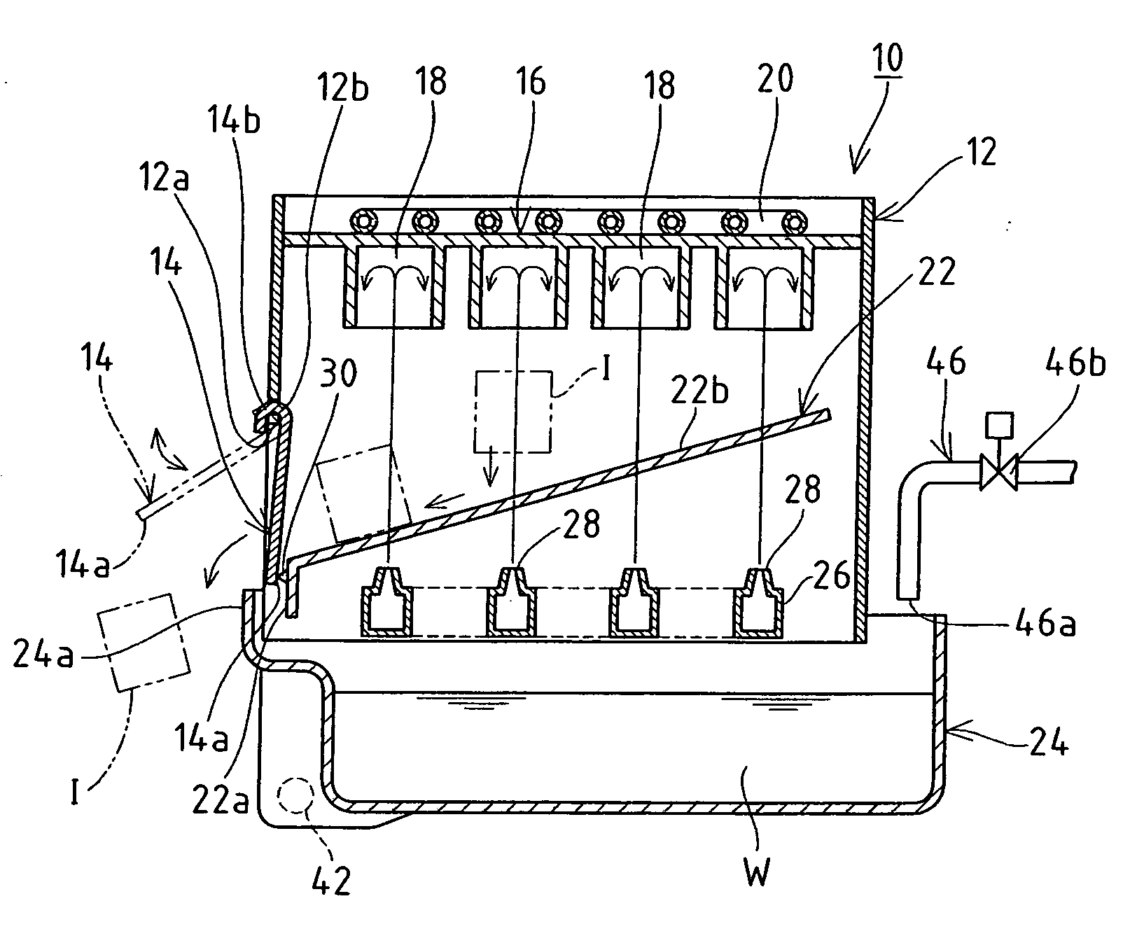
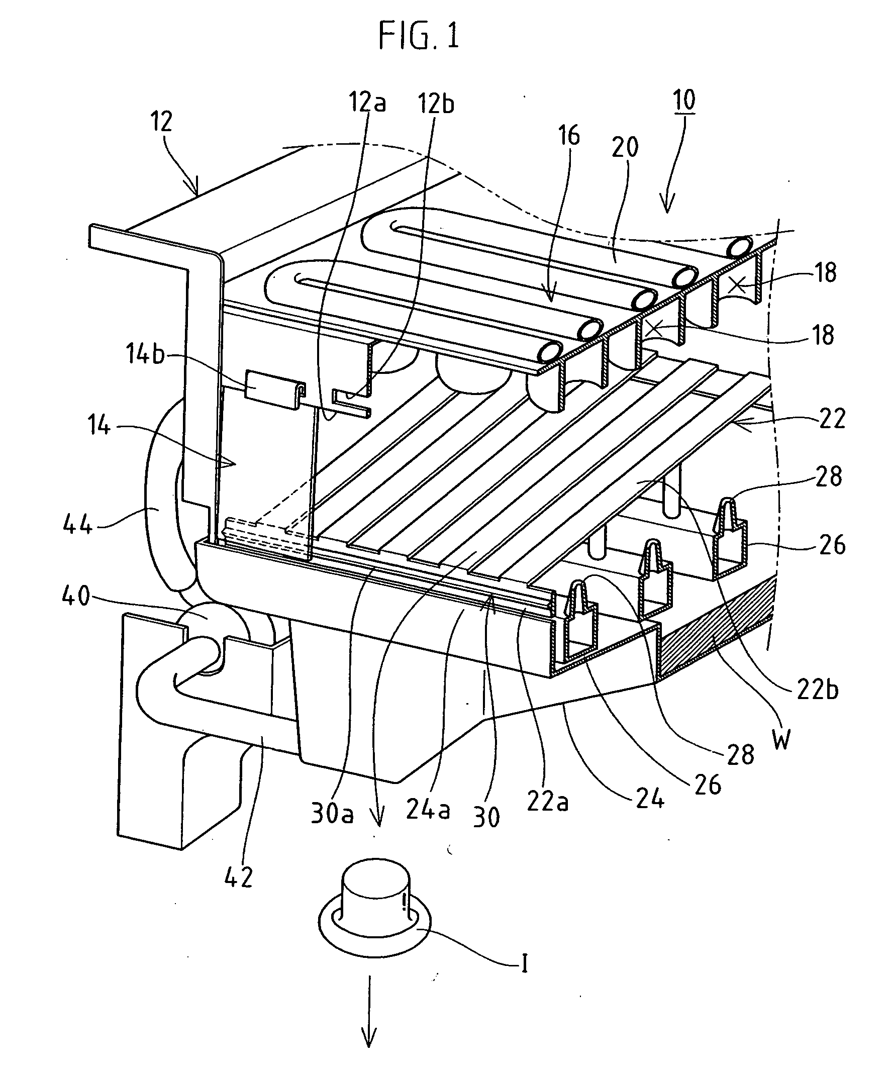
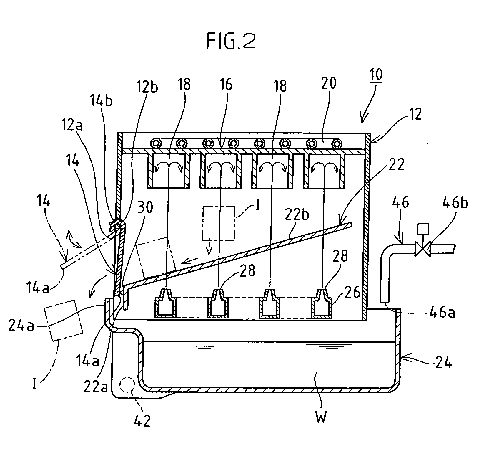
[0027] As shown in FIG. 1, an ice making mechanism 10 of an ice making machine according to a first embodiment comprises an ice making section case 12 on one side of which an opening 12a is provided to be closed by a separator 14 openably and closably. In the ice making section case 12, there are provided an ice making section 16 in which a large number of ice making chambers 18 opening downward are implemented on the upper side; a sprinkler 26 having a water sprinkling nozzle 28 provided corresponding to each of the ice making chambers 18; and an ice chute 22 provided to be inclined downward to the opening 12a of the ice making section case 12, between the ice making section 16 and the sprinkler 26, for leading an ice block I fallen from the ice making chamber 18 into sliding off toward the opening 12a. Also, an ice making water tank 24 is provided below the ice making section case 12 for retaining a given volume of ice making water W and for collecting unfrozen water. The lower en...
second embodiment
[0036]FIG. 4 or FIG. 5 shows an ice discharging structure according to a second embodiment. On the end face 22a of the ice chute 22 facing the opening 12a of the ice making section case 12, a plurality of second ribs 32 extending vertically are provided at a required interval in the width direction of the end face 22a, and tops 32a thereof and an inner face 14a of a separator 14 are configured so as to be in contact with each other. The second rib 32 is formed to have a triangular cross section, and the top 32a of the second rib 32 is in line contact with the inner face 14a of the separator 14. Between the inner face 14a of the separator 14 and the end face 22a of the ice chute 22, a second space 49 is formed between the adjacent second ribs 32, 32. Specifically, the ice making water W sprayed out in the ice making section case 12, led by the guide face 22b of the ice chute 22 or the separator 14, is collected in the ice making water tank 24 through the second space 49. Specifically...
third embodiment
[0037]FIG. 6 or FIG. 7 shows an ice discharging structure according to a third embodiment. On the inner face 14a of the separator 14, through the width direction thereof, a third rib 34 is provided, being configured so that the top 34a of the third rib 34 is in contact with the end face 22a of the ice chute 22. The third rib 34 is formed to have a triangular cross section, and the top 34a of the third rib 34 is in line contact with the end face 22a of the ice chute 22 facing the opening 12a of the ice making section case 12. Specifically, since the contact area of the contact part is small, the impact of the surface tension of the ice making water W getting through between the top 34a and the inner face 14a can be reduced. Also, a third space 50 is formed between the inner face 14a of the separator 14 and the end face 22a of the ice chute 22. Specifically, the ice making water W sprayed out in the ice making section case 12, led by the guide face 22b of the ice chute 22 or the separ...
PUM
 Abstract
Description
Claims
Application Information
 - R&D
- Intellectual Property
- Life Sciences
- Materials
- Tech Scout
- Unparalleled Data Quality
- Higher Quality Content
- 60% Fewer Hallucinations
Browse by: Latest US Patents, China's latest patents, Technical Efficacy Thesaurus, Application Domain, Technology Topic, Popular Technical Reports.
© 2025 PatSnap. All rights reserved.Legal|Privacy policy|Modern Slavery Act Transparency Statement|Sitemap|About US| Contact US: help@patsnap.com


