
Snow making method and apparatus

Inactive Publication Date: 2007-05-31
SNOW FAB SA
View PDF26 Cites 0 Cited by
  • Summary
  • Abstract
  • Description
  • Claims
  • Application Information

AI Technical Summary

Benefits of technology

[0010] The apparatus may be operable to pressurize the container above the static pressure coincident with the deflation of the at least one vessel. However, in a most preferred form of the invention, the pressure increase coincides with the deflation of the at least one vessel after every 10 to 15 cycles of inflation / deflation of the at least one vessel. This periodic increase of pressure provides greater effectiveness in breaking up the ice crystals within the vessel.
[0014] The at least one vessel may be provided with a discharge valve which operates in combination with the inflation source with the pressurized air / gas assisting in the flushing of snow and / or ice crystals through the vessel and out through the opening.
[0031] The method may also include manipulating the vessel to detach ice crystals from the inner wall of the vessel. The manipulation may be provided by inflating the flexible walled vessel by a source of pressurized gas applied internally to the vessel. The gas, which may be air may be permitted to bleed from the vessel to allow deflation. Furthermore, the flexible walled vessel may be subjected to external pressurization, for example, by being held within a pressure vessel, to assist in compressing the flexible walled vessel.

Problems solved by technology

One difficulty with this arrangement is that while snow and / or ice crystals are intended to form on the inner walls of the hoses, there is a risk that the ice crystals can form a solid block of ice which, once formed is difficult to dislodge.
This inevitably leads to downtime for the snow making apparatus and is also time consuming and physically demanding for the operator.

Method used


Image

  • Snow making method and apparatus
  • Snow making method and apparatus
  • Snow making method and apparatus

Examples


Embodiment Construction

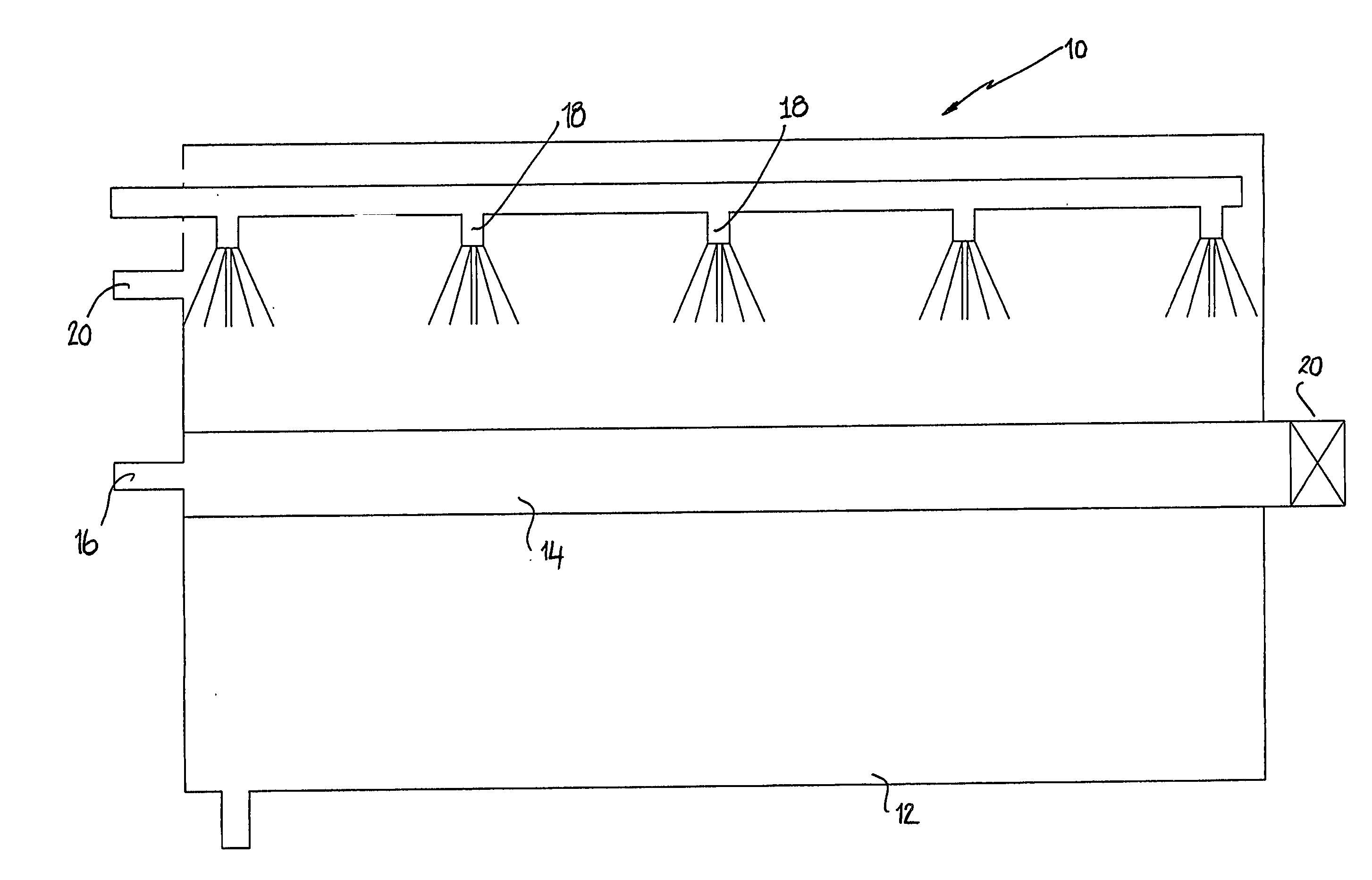
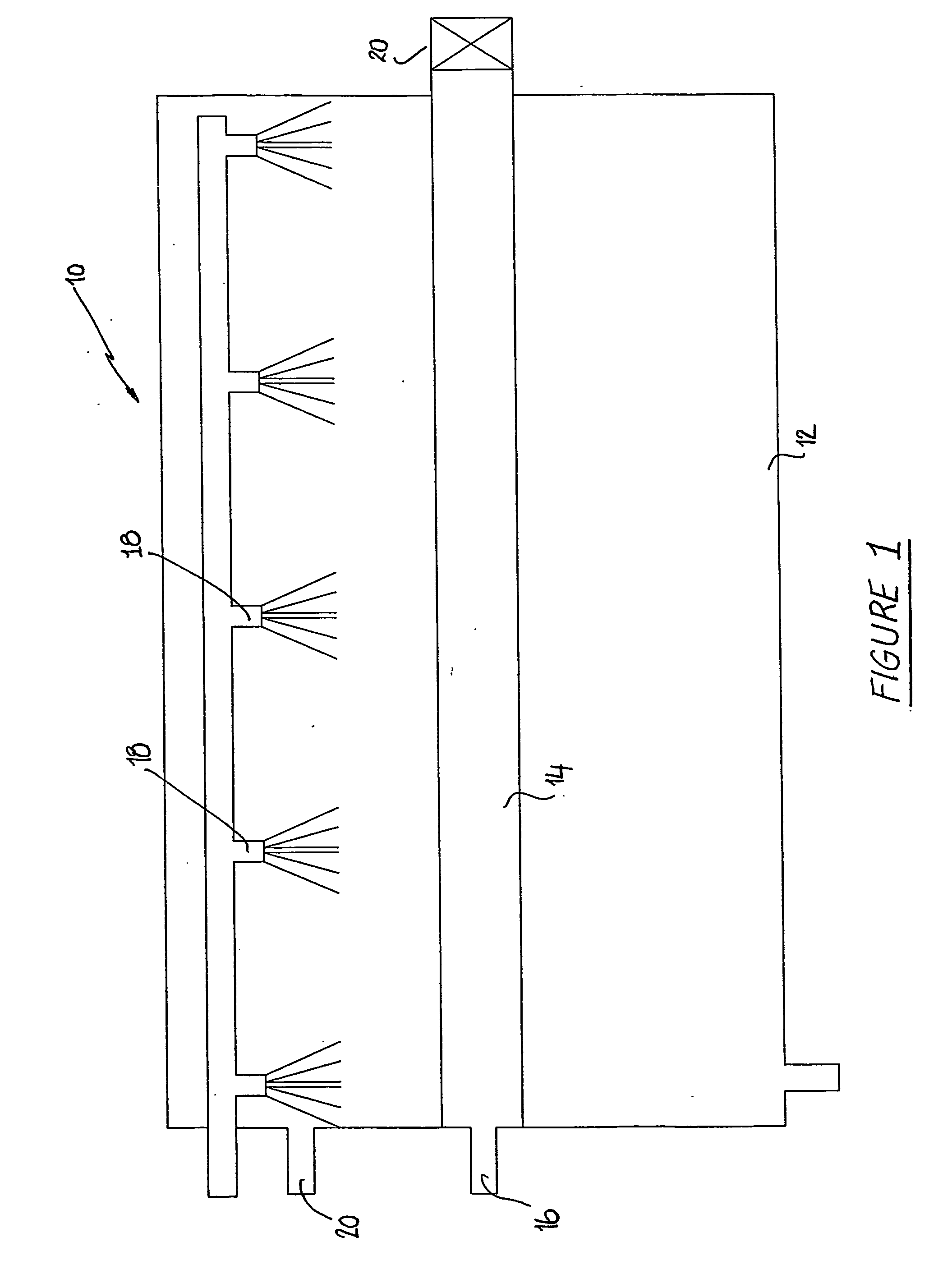
[0046]FIG. 1 show schematically, the operation of a snow making apparatus 10 according to the present invention. The snowmaking apparatus comprises a container such as pressure vessel or tank 12 which defines a cooling space 13. Extending through the cooling space are a number of flexible walled vessels such as hoses 14 of which only one is shown in the figure. The hoses 14 are connected to a water source as well as a source of pressurised air through inlet 16.

[0047] The pressure vessel 12 also includes a plurality of spray nozzles 18 which operate to spray a heat transfer medium eg. coolant such as glycol onto the hoses 14. Additionally, the cooling space 13 is pressurised to about 20 kPa above atmospheric pressure through the pressurising gas inlet 20. The conditions within the pressure vessel 12 are such that water within the hoses 14 is caused to freeze or to form snow and / or ice crystals on the internal walls of the hoses through the process of heat transfer through the walls ...


PUM


Abstract

An apparatus (10) for making snow or a snow-like substance includes a container (12) having a cooling space (13) adapted to contain pressurized air or gas of above atmospheric pressure. At least one flexible walled vessel (14) extends through the cooling space (13) and is connectable to a water source. The apparatus (10) is operable to maintain the cooling space at a sufficiently low temperature to at least partially freeze the water within the flexible walled vessel (14). As a preferred feature of the snow making apparatus, the apparatus may be adapted to maintain a static pressure within the cooling space of the container (12) and to periodically and temporarily increase the pressure within the cooling space to compress the flexible walled vessel (14). Invention also resides in an apparatus (10) for making snow or a snow-like substance, the apparatus including at least one flexible walled vessel (14) connectable to a water source. Spray equipment (18) sprays heat transfer medium onto the at least one flexible walled vessel (14) to chill the vessel sufficient to form ice crystals and / or snow within the vessel.

Description

FIELD OF THE INVENTION [0001] The present invention relates to an apparatus and a method for making snow or a snow-like substance. In particular, although not exclusively, the invention relates to a type of snow making apparatus, where snow is made within flexible-walled tubes by fluid transfer from a cooling medium surrounding the tubes. BACKGROUND OF THE INVENTION [0002] International Patent Application WO 02 / 37039 describes a snow making method and apparatus utilising a tank which is filled with liquid coolant. A number of flexible hoses are disposed within the tank. The hoses are filled with water and, through the process of heat transfer from the coolant, ice crystals form within the hoses. The hoses are periodically inflated to aid in dislodging the snow or ice crystals from the inner wall surfaces of the hoses. After each inflation, the hoses are permitted to deflate and this is aided by the pressure of the coolant in the tank. [0003] One difficulty with this arrangement is t...

Claims


Application Information

Patent Timeline
IPC IPC(8): F25J1/00F25C3/04
CPCF25C3/04F25C2303/044
Inventor BUCCERI, ALFIO
Owner SNOW FAB SA
Learn More