
LED lamp panel module

An LED light board and light board technology, which is applied to lighting and heating equipment, point light sources, lighting devices, etc., can solve the problems of difficult wiring of the light body and the difficulty involved in increasing the light board, so as to reduce the difficulty of design and use. The effect of increased area and easy wiring

Active Publication Date: 2015-11-11
SHENZHEN AOTO ELECTRONICS
View PDF25 Cites 0 Cited by
  • Summary
  • Abstract
  • Description
  • Claims
  • Application Information

AI Technical Summary

Problems solved by technology

[0005] The purpose of the present invention is to provide an LED light board module, which aims to solve the problem in the prior art that the increase in the number of lamp bodies leads to difficulty in wiring and increases the difficulty involved in the light board

Method used


Image

  • LED lamp panel module
  • LED lamp panel module
  • LED lamp panel module

Examples


Embodiment Construction

[0011] In order to make the object, technical solution and advantages of the present invention clearer, the present invention will be further described in detail below in conjunction with the accompanying drawings and embodiments. It should be understood that the specific embodiments described here are only used to explain the present invention, not to limit the present invention.

[0012] The implementation of this embodiment will be described in detail below in conjunction with specific drawings.

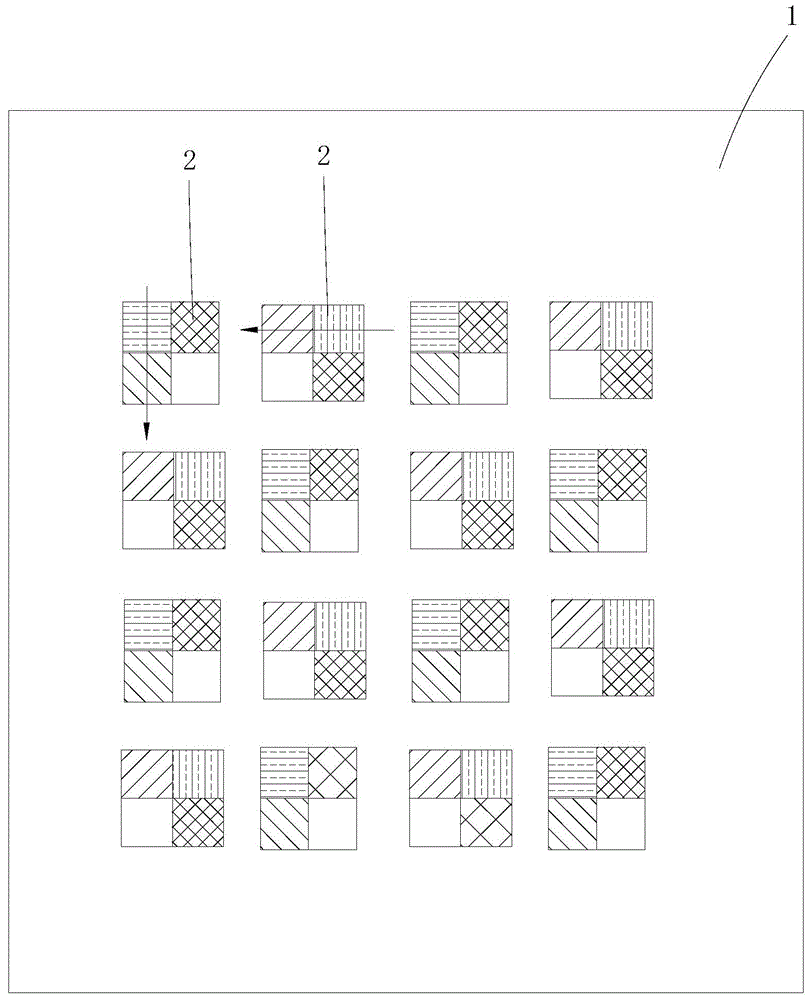
[0013] Such as figure 1 As shown, this embodiment provides an LED lamp panel module, including a lamp panel 1, on which a plurality of lamp bodies 2 are arranged in rows and columns, and provided with via holes (the via holes are known in the prior art mature structure, not shown in the figure).

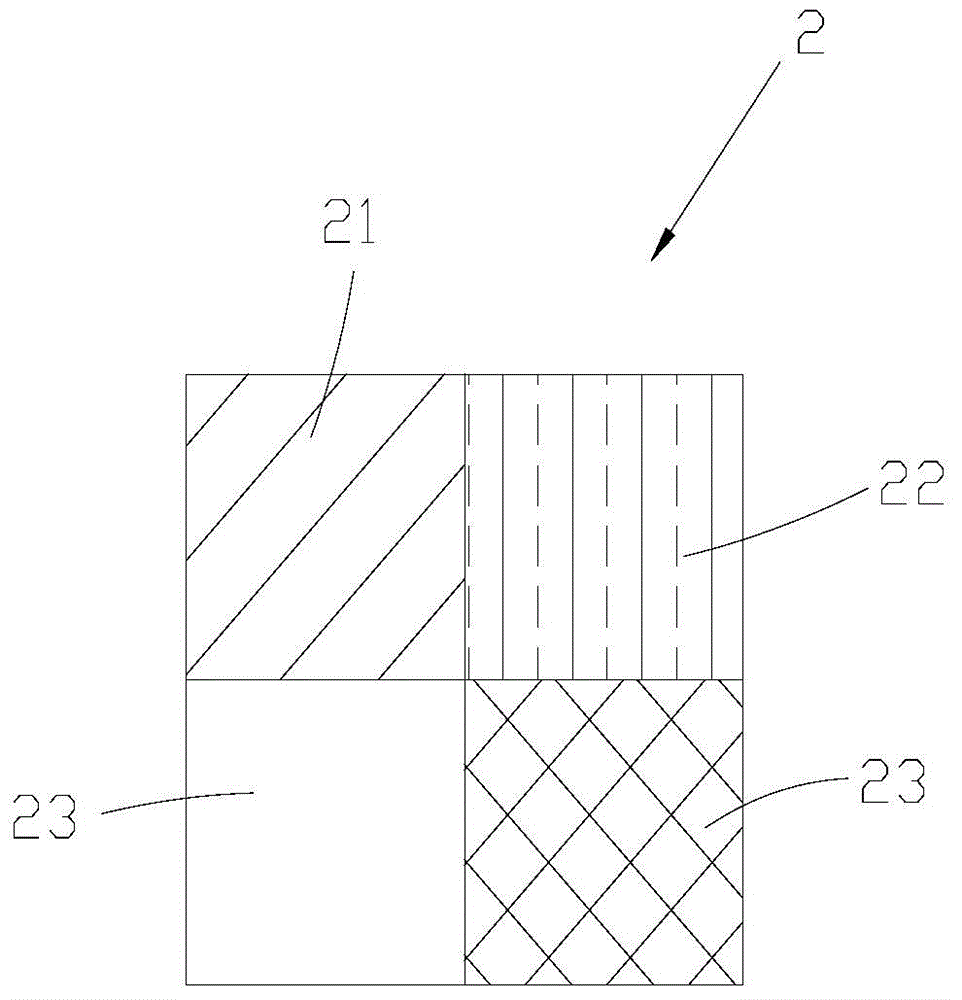
[0014] Such as image 3 As shown, each lamp body 2 is provided with a first monochrome lamp 21 , a second monochrome lamp 22 , a third monochrome lamp 23 and a power chip 24 arranged ...


PUM


Abstract

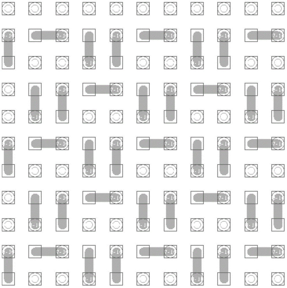
The invention relates to the technical field of LEDs, and discloses an LED lamp panel module. The LED lamp panel module comprises a lamp panel. The lamp panel is provided with a plurality of lamp bodies in rows and columns and provided with via holes. Each lamp body is sequentially provided with a first single-color lamp, a second single-color lamp, a third single-color lamp and a power supply chip clockwise in a surrounded manner, wherein the lamp body is installed in the direction in which the second single-color lamp points to the first single-color lamp. The included angle between the installation directions of any two adjacent lamp bodies on the lamp panel is 90 degrees or 180 degrees. According to the LED lamp panel module, the lamp bodies on the lamp panel can be installed in various directions, and a set of corresponding pins adjacent to each other are arranged between every two adjacent lamp bodies, so that direct wire routing is achieved, one via hole can be shared, the number of the via holes is reduced, and the lamp panel design difficulty is lowered.

Description

technical field [0001] The invention relates to the technical field of LEDs, in particular to an LED lamp panel module. Background technique [0002] The LED display is composed of multiple light bodies integrated on the light board module. Each light body is integrated with three single-color light chips (red, yellow, blue) and power chips, which drive different single-color lights on each light body. When the colored lights are on, various pictures can be displayed on the LED display. With its advantages of high brightness, true color reproduction, seamless splicing, and point-by-point correction, LED display screens have strong competitive strength in the market, and have more opportunities to apply to control rooms, TV studios, command and dispatch centers, and large conference centers. Entering into the high-end market, it is even very likely to gradually replace the market position of traditional indoor DLP rear projection and LCD splicing walls in the future. [000...

Claims


Application Information

Patent Timeline
Patent Type & Authority Applications(China)
IPC IPC(8): F21S8/00F21V19/00F21V23/00F21Y101/02
CPCF21S8/00F21V19/001F21V23/001F21V23/003
Inventor 肖道粲韦艳引何昆鹏刘玲吴振志吴涵渠
Owner SHENZHEN AOTO ELECTRONICS
Learn More