Optimizing photovoltaic-electrolyzer efficiency

a photovoltaic and electrolyzer technology, applied in the direction of electrolyzers, instruments, energy inputs, etc., can solve the problems of particularly variable ambient temperature and solar irradiance of the pv system, and achieve the effect of efficient hydrogen production

Inactive Publication Date: 2007-05-31
GM GLOBAL TECH OPERATIONS LLC
View PDF7 Cites 249 Cited by
  • Summary
  • Abstract
  • Description
  • Claims
  • Application Information

AI Technical Summary

Benefits of technology

[0010] Methods are provided for design and / or operation of a solar-powered photovoltaic-electrolyzer system for efficient production of hydrogen from water. The methods are applicable generally to electrolyzer systems and photovoltaic systems. The aim of the methods is to enable each separate system, photovoltaic and electrolyzer, to operate efficiently in their combination.
[0011] The electrolyzer is sized based on a design hydrogen production rate. The hydrogen production rate will permit calculation of an operating direct current (Ioper) and a specification of a number of electrolytic cells connected in series. Some electrolyzer cells may also be arranged in parallel electrical connection. The operating voltage (Voper) will be estimated from the number of cells in electrical series connection. Testing of the system will provide accurate confirmation of operating current and voltage values for the electrolyzer and a suitable operating temperature or temperature range for most efficient operation of the electrolyzer. A goal of the practice of this invention is to provide a photovoltaic (PV) system for powering the specified electrolyzer such that the PV system is able operate at a most efficient voltage level in delivering direct current power to the electrolyzer.
[0015] Often the operating temperature of photovoltaic modules increases during operation and reduces their electrical output. Cooling of the modules (by spray of a cooling fluid or the like) can be used to maintain their operation at a desired maximum power point.

Problems solved by technology

For example, the operation of the PV system is particularly subject to variation in ambient temperature and solar irradiance.

Method used


Image

  • Optimizing photovoltaic-electrolyzer efficiency
  • Optimizing photovoltaic-electrolyzer efficiency
  • Optimizing photovoltaic-electrolyzer efficiency

Examples


example optimization case 1

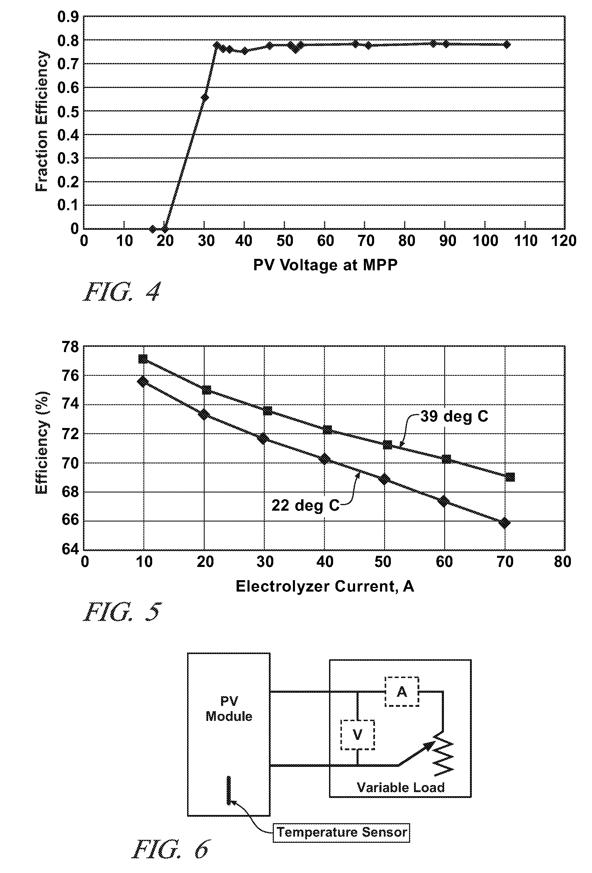
[0091] For the PV module (Sanyo HIP-190) that we tested using the electronic variable load system as shown in FIGS. 7 and 8, we found that the measured:

Voltage at the MPP (Vmpp)=52 volts at 41° C. [from FIG. 7] [the Vmpp at STC, 25° C., was 54.8 volts from the manufacturer specifications]

Power at MPP (Pmax)=180 Watts 41° C. [from FIG. 7][the Pmax at STC was 190 W from the manufacturer specifications]

The maximum power current (Impp) from each PV module will be 180 Watts / 52 volts=3.46 amps at 41° C.

Temperature coefficient of Pmax (% of total P / ° C.)=−0.30% [from FIG. 8] [the coefficient was also −0.30% % of total P / ° C. from the manufacturer specifications]

Temperature coefficient of Vmpp (volts / ° C.)˜0.3%×180 VA / 3.46 A=0.16 volts / ° C.

Case 2—Control Example (Not to be Optimized):

[0092] All PV module parameters were the same as Case 1.

Step 5—

[0093] Next, the effect of electrolyzer operating voltage on the efficiency of solar-powered photovoltaic-electrolyzer systems for generating h...

case 2

l Example (Not to be Optimized):

[0104] Nothing is done to change the voltage, current output, or temperature of the PV system.

In Optimization Case 3:

[0105] The steady state operating temperature in another cool sunny period is 41° C. All the electrolyzer parameters are the same as Case 1 except that the redesigned electrolyzer in this case (Case 2) has 25 electrolysis cells connected in series giving a Voper of 45 volts.

[0106] The PV module was redesigned to have 83 solar cells in series to produce a Vmpp of 45 volts at 41° C. [The original PV module in Case 1 had 96 solar cells connected in series to give 52 volts at 41° C.]

In Optimization Case 4:

[0107] All the electrolyzer parameters are as described in Case 1.

[0108] At the PV operating temperature, the only PV modules available for use have a Vmpp of 36 volts.

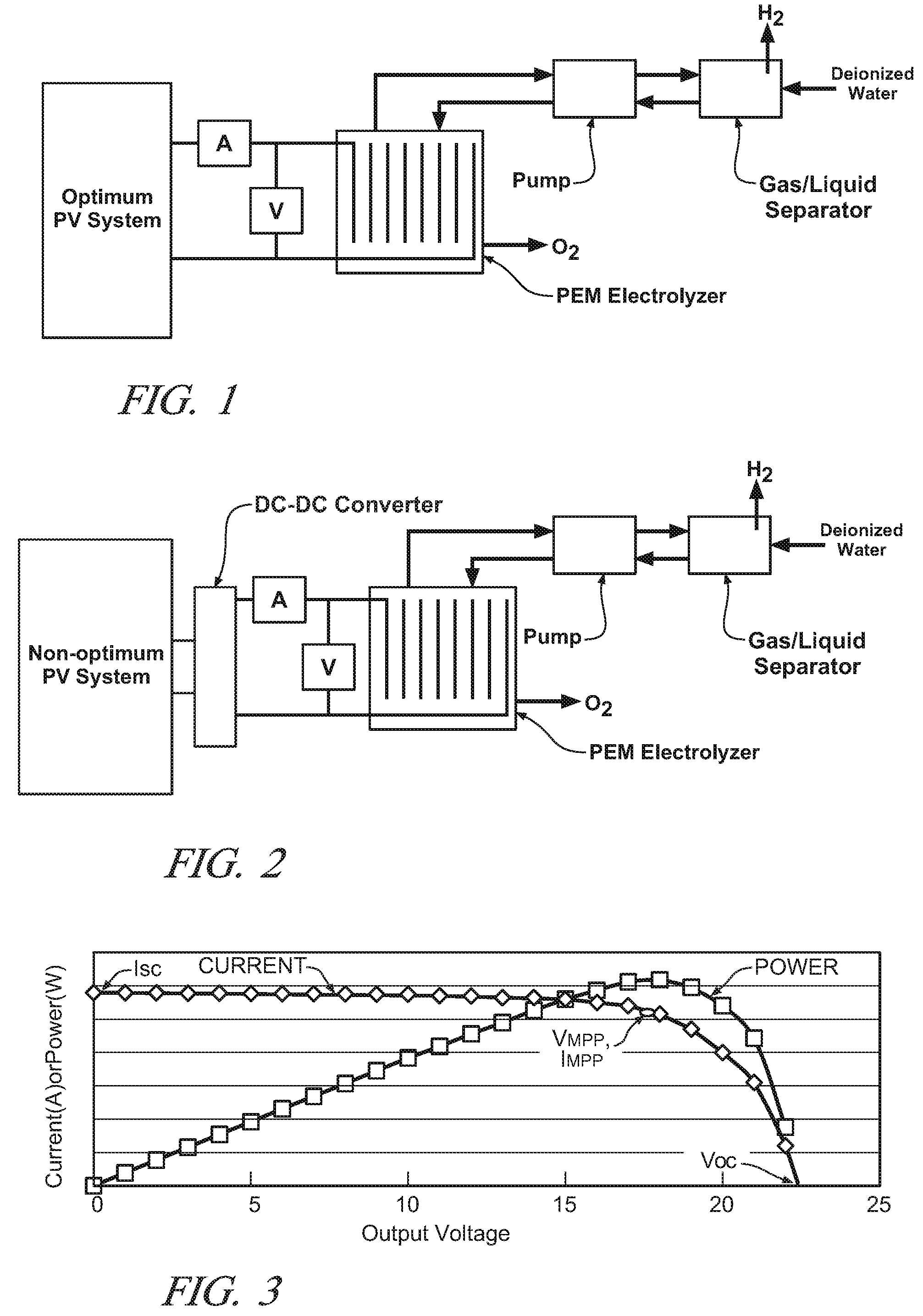
[0109] The PV modules are connected to a DC-DC converter or charge controller system with an input voltage range that includes 36 volts (30-40 volts for example) and...

case 1

In

[0113] The electrolyzer efficiency is 70%. [0114] The PV system efficiency is 18.2% [0115] The overall solar energy to hydrogen conversion efficiency is 12.7% [0116] The hydrogen production rate is 0.10 kg / hour. [0117] The PV cell area is 26×1.027 m2=26.7 m2. (measured area of the PV cells, usually obtainable from the manufacturer)

In Case 2—Control Example (Not to be Optimized): [0118] The electrolyzer efficiency is 62%. [0119] The PV system efficiency=150 watts / 190 watts×19%=15% [0120] The overall solar energy to hydrogen conversion efficiency is 9% Hydrogen⁢ ⁢rate=Ioper / (N×26,806⁢ ⁢amps⁢ / ⁢kg⁢ / ⁢hour)=111×20 / 26⁢,⁢806=0.083⁢ ⁢kg⁢ / ⁢hour[0121] The PV cell area is 30×1.027 m2=30.8 m2.

[0122] Because the electrolyzer and the PV system were both not optimized Case 2 required a greater number, area, and cost of PV modules but produces less hydrogen per hour.


PUM

PropertyMeasurementUnit
temperatureaaaaaaaaaa
DC voltageaaaaaaaaaa
temperaturesaaaaaaaaaa

Abstract

An array of photovoltaic (PV) module(s) is arranged in series and / or parallel electrical connection to deliver direct current electrical power to an electrolyzer to produce hydrogen. The electric power is delivered by the array at its maximum power point (Vmpp) to deliver Ioper at Voper for the electrolyzer. The arrangement of the PV modules in the array, or the arrangement of cells in the electrolyzer, is continually monitored and controlled by an automatic controller system to operate the PV and electrolyzer systems at or near their respective maximum efficiencies. A DC-DC converter may be used to adjust the Vmpp to the operating voltage of the electrolyzer.

Description

CROSS REFERENCE TO RELATED APPLICATIONS [0001] This application is a continuation-in-part of co-pending application Ser. No. 11 / 049213, titled “Method and Apparatus for Hydrogen Generation,” and filed Feb. 2, 2005. The disclosure of this parent application is incorporated herein by reference. The parent application also claims priority based on U.S. provisional application 60 / 545,379, filed Feb. 14, 2004. [0002] This application also claims priority based on provisional application 60 / 750691, filed Dec. 15, 2005, titled “Methods for Optimizing Photovoltaic-Electrolyzer Efficiency to Generate Hydrogen,” and which is incorporated herein by reference.TECHNICAL FIELD [0003] This invention pertains to hydrogen production by electrolytic decomposition of water. More specifically this invention pertains to optimized use of photovoltaic modules to supply power for electrolytic production of hydrogen from water. BACKGROUND OF THE INVENTION [0004] As disclosed in the above identified parent a...

Claims


Application Information

Patent Timeline
Patent Type & Authority Applications(United States)
IPC IPC(8): C25B1/02C25B1/04C25B15/00H01L31/04
CPCC25B1/04C25B15/00Y02E60/366Y02E70/10Y02E60/36Y02P20/133
Inventor GIBSON, THOMAS L.KELLY, NELSON A.
Owner GM GLOBAL TECH OPERATIONS LLC
Why Eureka
Try Eureka