Push latch

Inactive Publication Date: 2007-05-31
ILLINOIS TOOL WORKS INC
View PDF11 Cites 25 Cited by
  • Summary
  • Abstract
  • Description
  • Claims
  • Application Information

AI Technical Summary

Benefits of technology

[0010] An advantage of the present invention is providing a push latch that is simple in operation with few moving parts.
[0011] Another advantage of the present invention is providing a push latch having stabilizers to improve stability of the latch when closed.
[0012] Still another advantage of the present invention is providi

Problems solved by technology

A problem with push-style latches of this type is that the pawl or arm may be caused to retract at an undesirable time.
Some known prior art latches are complex with relatively many individu

Method used


Image

  • Push latch
  • Push latch
  • Push latch

Examples


Embodiment Construction

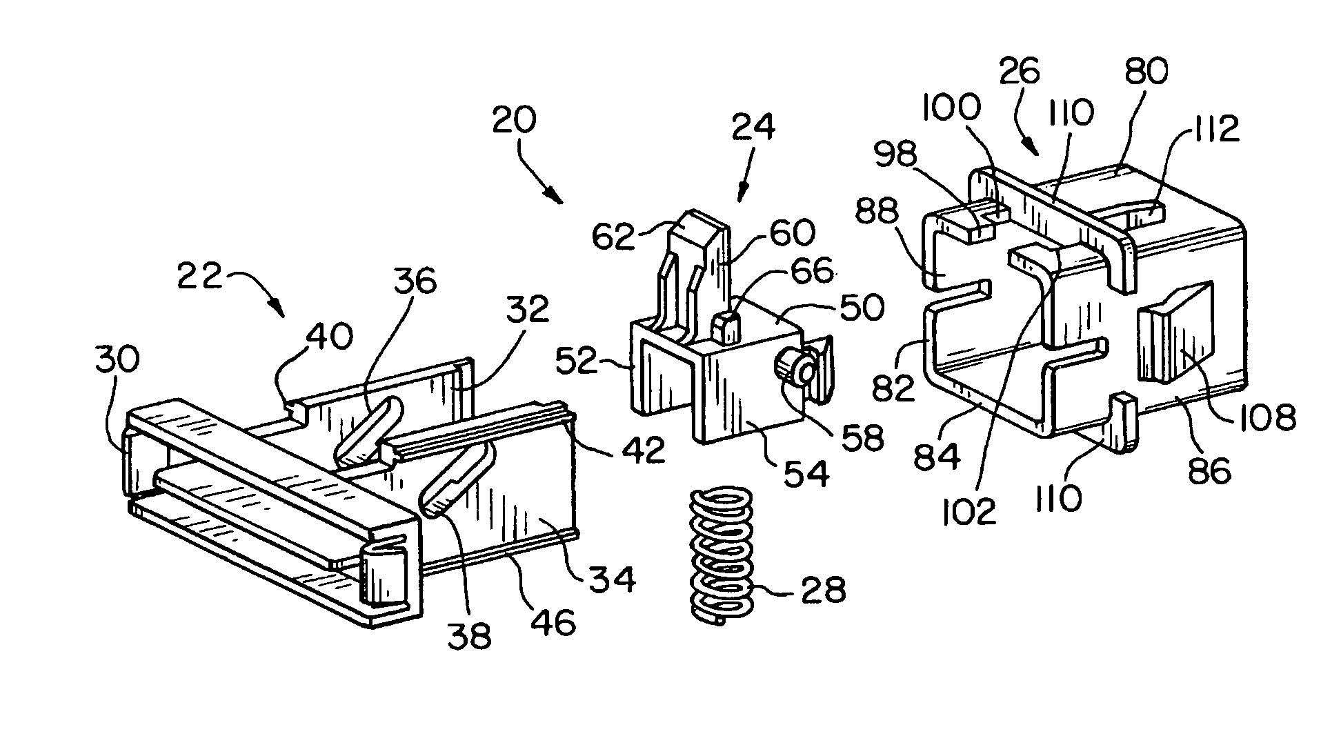
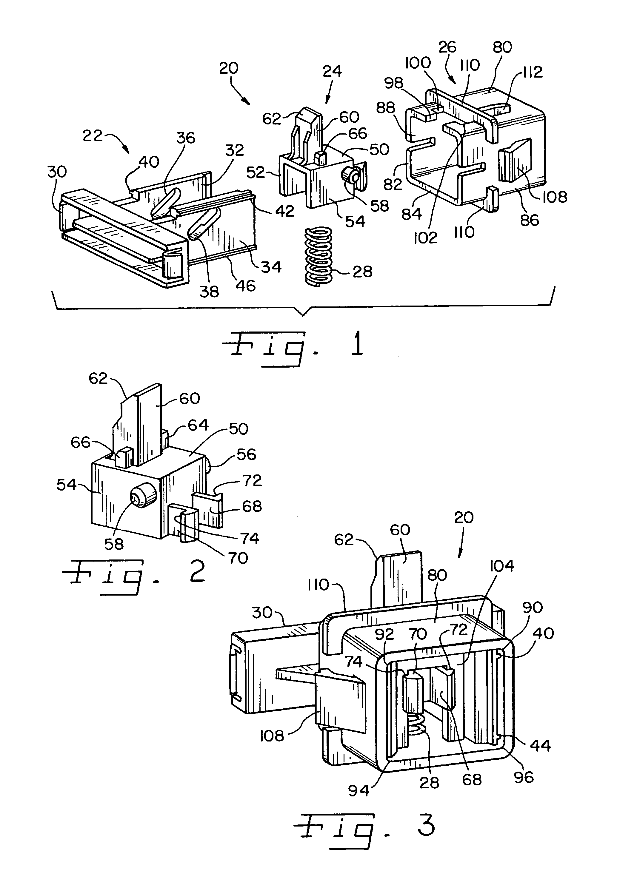
[0025] Referring now more specifically to the drawings and to FIG. 1 in particular, numeral 20 designates a push-button latch in accordance with the present invention. Latch 20 includes an actuator 22, a lock 24, a housing 26 and a spring 28.

[0026] Actuator 22 includes a push button 30 which can be configured to hold a decorative panel or the like, or can be complete on its own. Push button 30 is the readily accessible portion of latch 20 accessed by a user to release latch 20. Push button 30 in the exemplary embodiment is a rectangular elongated body; however, those skilled in the art should readily recognize that push button 30 can be of different sizes, shapes and the like, including for example, round, square, rectangular or the like. Actuator 22 further includes first and second arms 32 and 34, respectively, which form a monolithic structure with push button 30. First and second arms 32, 34 are disposed in spaced relation one to the other and define therein first and second sl...


PUM


Abstract

A push button latch includes a housing, an actuator movable along a path substantially axial of the housing and a lock movable along a path transverse to the axial path. A spring biases the lock to a latching position, and structures in the lock and housing inhibit unintended opening of the latch.

Description

CROSS-REFERENCE TO RELATED APPLICATIONS [0001] The present regular United States Patent Application claims the benefits of U.S. Provisional Application Ser. No. 60 / 736,494 filed on Nov. 14, 2005.FIELD OF THE INVENTION [0002] The present invention relates generally to latches and, more particularly, the invention pertains to push style latches commonly used to secure compartment doors, bins, glove boxes, and the like. BACKGROUND OF THE INVENTION [0003] Latches are used extensively on various types of bins and enclosures. Latches are used extensively in the automotive industry, with each individual automobile potentially having several latched areas, such as glove boxes, consoles, storage bins and the like. It is known to employ latches that include a pawl or arm-like member that engages a mating structure such as the bin door when the door is in a closed position. It is known further to use push-button releases on a latch to retract the pawl or arm to allow the device to open. Upon r...

Claims


Application Information

Patent Timeline
IPC IPC(8): E05C1/08
CPCE05B83/30E05C1/14E05B83/32Y10S292/37Y10T292/0969Y10T292/0976
Inventor BELLA, JOSEPH J.
Owner ILLINOIS TOOL WORKS INC
Why Eureka
Try Eureka