Identification band using a conductive fastening for enhanced security and functionality

a technology of conductive fastening and identification band, which is applied in the direction of burglar alarm by disturbance/breaking of stretched cords/wires, instruments, etc., can solve the problems of difficult repair of broken trace and typical fragility of conductor, and achieve the effect of increasing the security of the wristband and improving the acceptability of the user

Inactive Publication Date: 2007-05-31
BARTRONICS HONG KONG
View PDF68 Cites 46 Cited by
  • Summary
  • Abstract
  • Description
  • Claims
  • Application Information

AI Technical Summary

Benefits of technology

[0017] In one specific implementation, the fastening becomes electrically coupled to the disabling wire at whichever point in the band the fastening is engaged, thereby shorting out the remainder of the disabling wire's path. In this embodiment, the disabling wire may be cut at any point beyond where the fastening is engaged without disrupting RFID functionality. This allows the wearer of the band to trim excess band material at the end of the band, such as with a pair of scissors or the like. The removal of excess band material is typically done with disposable plastic bands that utilize this sort of fastening mechanism, and the ability to do the same with a secure RFID wristband improves its acceptability to the user.
[0018] In an alternative embodiment, the RFID circuit itself is embedded into the fastening mechanism. This prevents an individual from enabling the RFID transponder to function by creating an electrically continuous path between two of the provided contact points for the fastener, because this action would short circuit the RFID circuit. This increases the security of the wristband to attempts to improperly enable the RFID transponder.

Problems solved by technology

The conductor is typically fragile so as to make repair of a broken trace more difficult.

Method used


Image

  • Identification band using a conductive fastening for enhanced security and functionality
  • Identification band using a conductive fastening for enhanced security and functionality
  • Identification band using a conductive fastening for enhanced security and functionality

Examples


Embodiment Construction

[0028] A description of preferred embodiments of the invention follows.

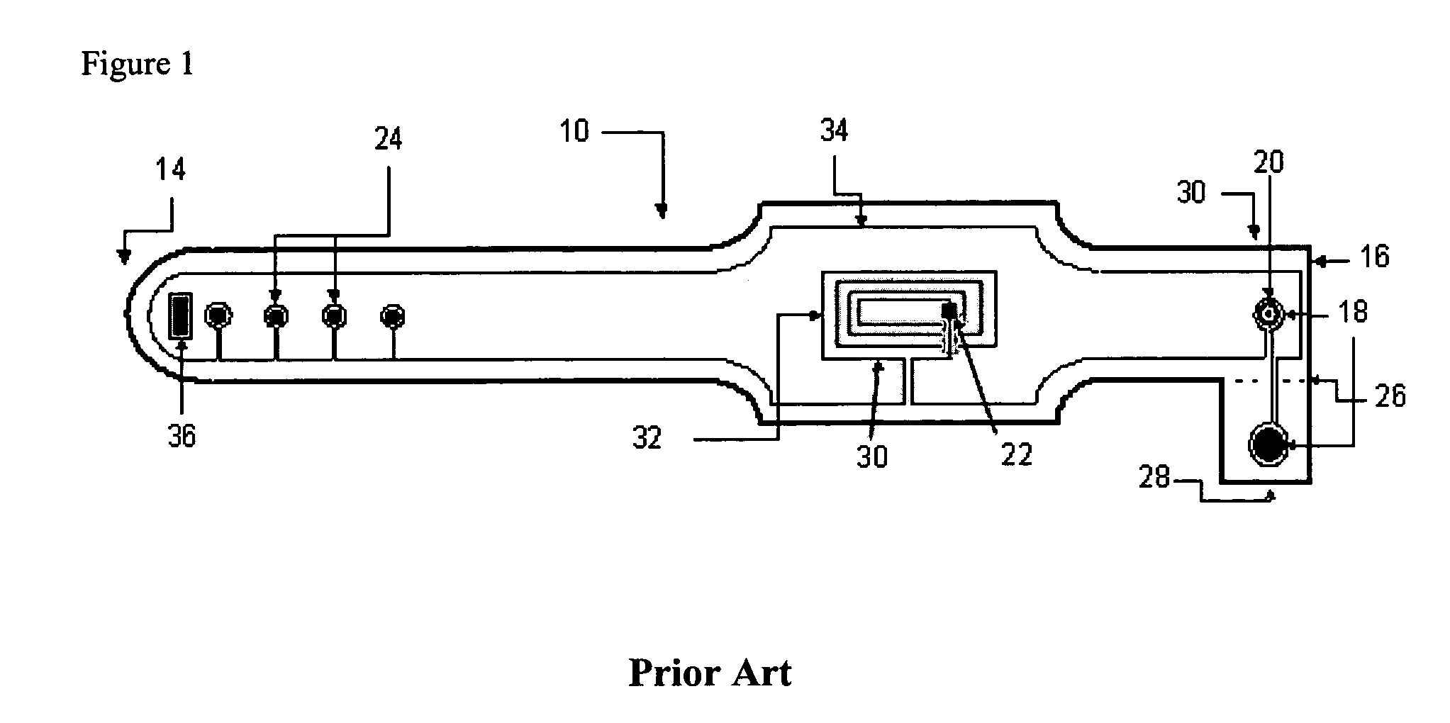
[0029]FIG. 1 is a general illustration of a disabling Radio Frequency Identification (RFID) bracelet 10, as known in the art, in the form of elongated band 12 with opposite ends 14, 16 that can be brought together and fastened to form a closed loop. Bracelet 10 comprises a mechanical non-reusable tamper-resistant locking mechanism 18 to fasten the opposite ends 14, 16 together and to prevent the user from attempting to open the locking mechanism 18 to remove the bracelet 10 without rendering those tampering efforts visually obvious. Locking mechanism 18 comprises a barbed peg 20 and a locking hole 21 in flap 28 at one end of said band and at least one adjustment opening or adjustment hole 24 at the opposite end of said band. Adjustment holes 24 can be used to adjust the bracelet 10 to conform to body parts of different circumferences. When ends 14, 16 are brought together, the barbed peg 20 is arranged to pass t...


PUM


Abstract

An identification device formed from a band of material and a non-reusable tamper-resistant fastening arranged to join opposite end regions of the band. A Radio Frequency Identification (RFID) transponder is disposed in the band. The transponder includes and RFID circuit, such as may be formed on an integrated circuit (IC) chip, and an antenna. In the present invention, the tamper-resistant fastening serves additional functions beyond securing the opposite end regions of the band together. Namely, the fastening can be made of a conductive material and designed to create electrical continuity between multiple conductors to enable or disable certain circuit functionality. In one variation, this continuity allows the excess tail portion of the wristband to be cut without disrupting circuit functionality. In another variation, the fastening mechanism is designed to crimp conductors together. In yet another embodiment, the RFID circuit itself is wholly or partially formed within the fastening mechanism to increase the better protect and support the circuit, as well as to make it more difficult to defeat the tamper-resistant functionality of the device.

Description

FIELD OF THE INVENTION [0001] The present invention relates to a non-reusable identification device that may be used to identify persons or articles. BACKGROUND OF THE INVENTION [0002] Disposable bracelets have long been used for such things as identification, access control, age verification, among other purposes. Such bracelets have typically been made from materials such as polyester, paper, or vinyl. The physical presence of a bracelet of particular color or design is traditionally used as its identifier. For example, such bracelets have been used in water parks and theme parks to quickly and uniquely identify patrons who have already paid for admission, or to control access to restricted areas. A patron of legal drinking age could obtain a bracelet to indicate that the patron is of legal age, granting the patron access to restricted areas such as beer sales areas. [0003] In recent years, such bracelets have been augmented with Radio Frequency Identification (RFID) technology. R...

Claims


Application Information

Patent Timeline
Patent Type & Authority Applications(United States)
IPC IPC(8): G08B13/14
CPCG06K19/04G06K19/07749G06K19/07762G08B21/0286
Inventor LERCH, JOHN W.GIRVIN, JOSHUA M.NORAIR, JOHN P.
Owner BARTRONICS HONG KONG
Why Eureka
Try Eureka