Extractor For Broken Bone Screws

a bone screw and screw extraction technology, applied in the field of bone screw extraction devices, can solve problems such as bone loss, and achieve the effect of reducing the loss of host bon

Inactive Publication Date: 2007-05-31
S S WHITE TECH
View PDF11 Cites 34 Cited by
  • Summary
  • Abstract
  • Description
  • Claims
  • Application Information

AI Technical Summary

Benefits of technology

[0009] Accordingly, an object of the present invention is to provide a device for removing broken bone screws which can do so in a single step with reduced loss of host bone.

Problems solved by technology

Such hole saw devices have the disadvantage of removing a relatively large core of host bone, resulting in considerable bone loss.

Method used


Image

  • Extractor For Broken Bone Screws
  • Extractor For Broken Bone Screws
  • Extractor For Broken Bone Screws

Examples


Embodiment Construction

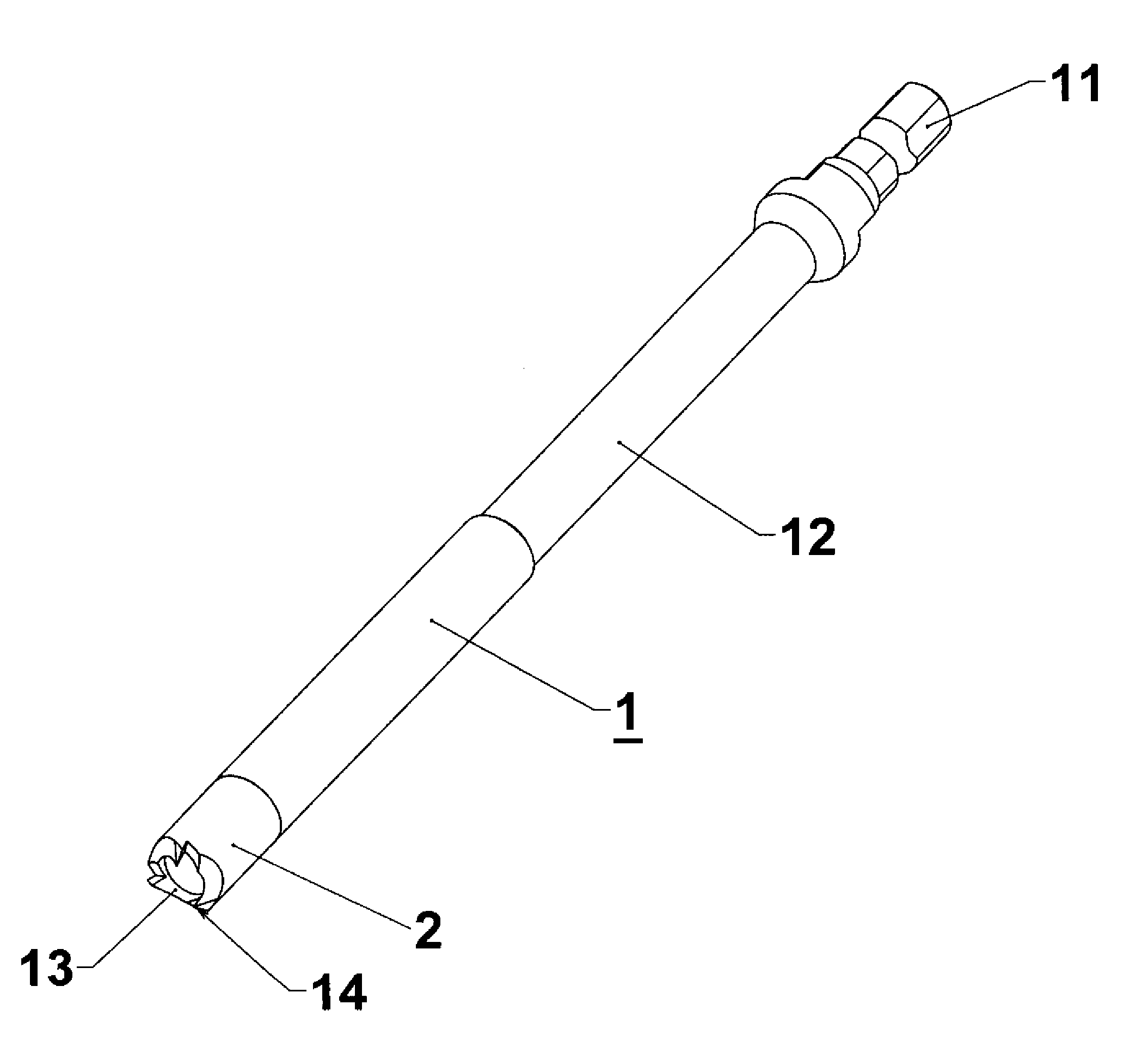
[0023] As seen in FIG. 1, the broken bone screw removal device 1 has a proximal end 11 for receiving a rotating tool such as a drill chuck, an elongated shaft portion 12, and a trephine end assembly 2.

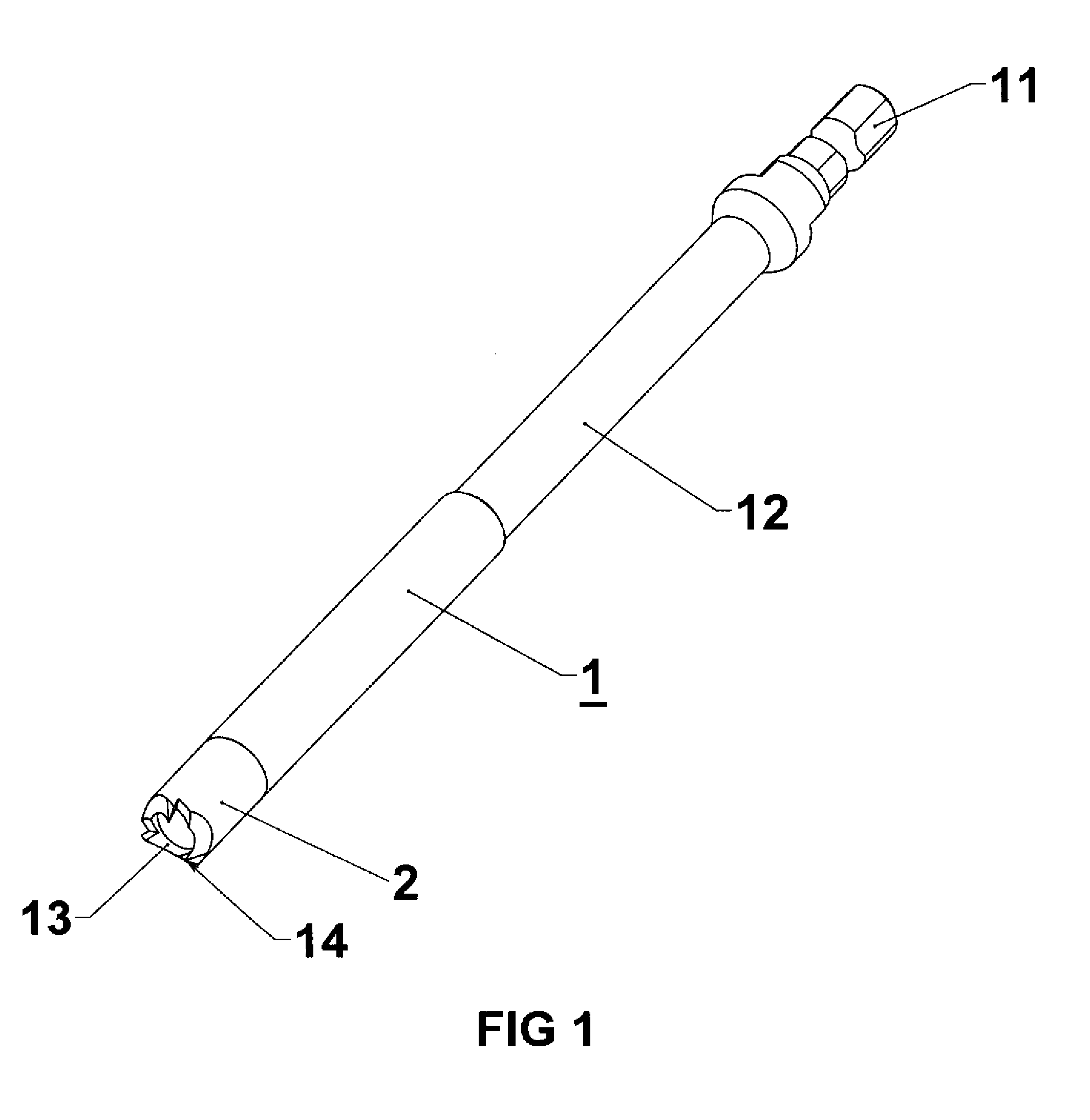
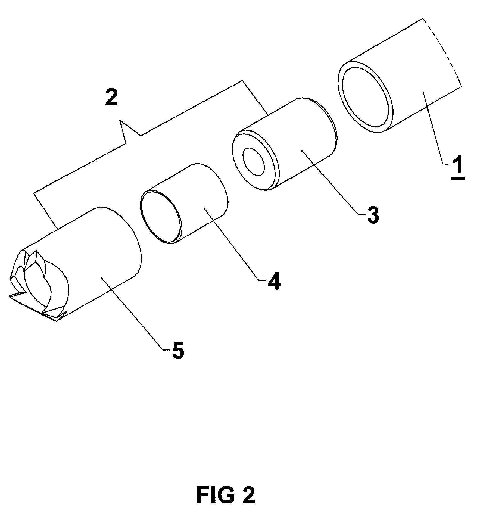
[0024] The trephine assembly 2 includes an internal cam 4 and a trephine 5 which is attached to the end portion of the device 1, as shown in FIGS. 1, 2 and 3B. The end assembly has a distal end 13 comprising a cutting tip with sharp edged teeth 14.

[0025] As shown in FIGS. 2 and 3B, the trephine end assembly 2 includes an alignment pin 3 which extends between aligned holes in the trephine 5 and adjacent end portion of the device 1 to axially align the same with each other.

[0026] A portion of the alignment pin 3, and a cam 4 are housed inside the trephine 5, which is rigidly attached to the end portion of the device 1 as shown in FIG. 3B.

[0027] The cam 4 is free to rotate within the trephine 5. As shown in FIGS. 3A and 3B, the cam 4 is in the form of an annular, i.e. cylindrical shel...


PUM


Abstract

A generally cylindrical broken bone screw removal device having a trephine assembly located at the distal end and a proximal end adapted to be engaged by a tool for rotating the device. The trephine assembly has a trephine, an alignment pin, and an internal annular cam. The cam is free to rotate independent of the trephine. The internal wall of the cam has a D shaped cross-section which is tapered, i.e. decreases in size from the distal toward the proximal end of the device. The internal diameter of the trephine is eccentric to its outer diameter, and the D shaped cross-section of the cam is eccentric to the internal diameter of the trephine. A broken screw is removed from bone by placing the trephine over the proximal end of the screw and rotating the device while applying pressure to cause the trephine to core bone around the screw, so that the device descends down the body of the screw until the screw to enters the interior of the cam to a depth where it engages the tapered walls of the cam and causes the cam to rotate with respect to the adjacent internal wall of the trephine; and the body of the screw becomes wedged between the cam internal wall of the trephine to transmit torque from the device to the screw to unscrew it from the bone.

Description

CROSS-REFERENCE TO RELATED APPLICATION [0001] This application claims the benefit of U.S. Provisional Application Ser. No. 60 / 730,605 filed Oct. 25, 2005 [the filing receipt has a date of Oct. 27, 2005 and a request for correction of that date has been made) and entitled Extractor for Broken Bone Screws.BACKGROUND OF THE INVENTION [0002] The present invention relates to a device for removing bone screws which are embedded in bone and which have their heads detached. [0003] Although primarily intended for use in removing broken bone screws, the device of the present invention can also be used for removing any embedded cylindrical object such as a drill bit, reamer, or tap; or similar devices which are frequently used in orthopedic surgery. The device is intended to remove a broken screw regardless of whether it stands proud of the bone surface. [0004] Bone screws are often used in orthopedic surgery to secure bone sections to each other or to artificial joints, plates or other struct...

Claims


Application Information

Patent Timeline
Patent Type & Authority Applications(United States)
IPC IPC(8): A61F2/00
CPCA61B17/1637A61B17/92
Inventor RUPP, GLENN A.KLIMASH, MATTHEW C.
Owner S S WHITE TECH
Why Eureka
Try Eureka