Standby arrangement for power supplies

a technology for power supplies and standby power, which is applied in the direction of liquid/fluent solid measurement, television system, instruments, etc., can solve the problems of increasing the cost of products, increasing the standby power consumed by products, and being recognized as very large the total standby power consumption of such products, and achieves low standby power consumption and convenient powering.

Inactive Publication Date: 2007-05-31
POWER INTEGRATIONS INC
View PDF4 Cites 91 Cited by
  • Summary
  • Abstract
  • Description
  • Claims
  • Application Information

AI Technical Summary

Benefits of technology

[0011] The first control unit can be conveniently powered from the power supply input via a resistor and a shunt regulator to provide a very low standby power consumption.

Problems solved by technology

Although the standby power requirements of an individual consumer electronics product may be small compared with the operating power requirements, this standby power is consumed continuously, and there is a great number of such products, so that the total standby power consumption of such products is recognized as being very large.
The standby power supply increases the cost of the product and also increases the standby power consumed by the product.

Method used


Image

  • Standby arrangement for power supplies
  • Standby arrangement for power supplies
  • Standby arrangement for power supplies

Examples


Embodiment Construction

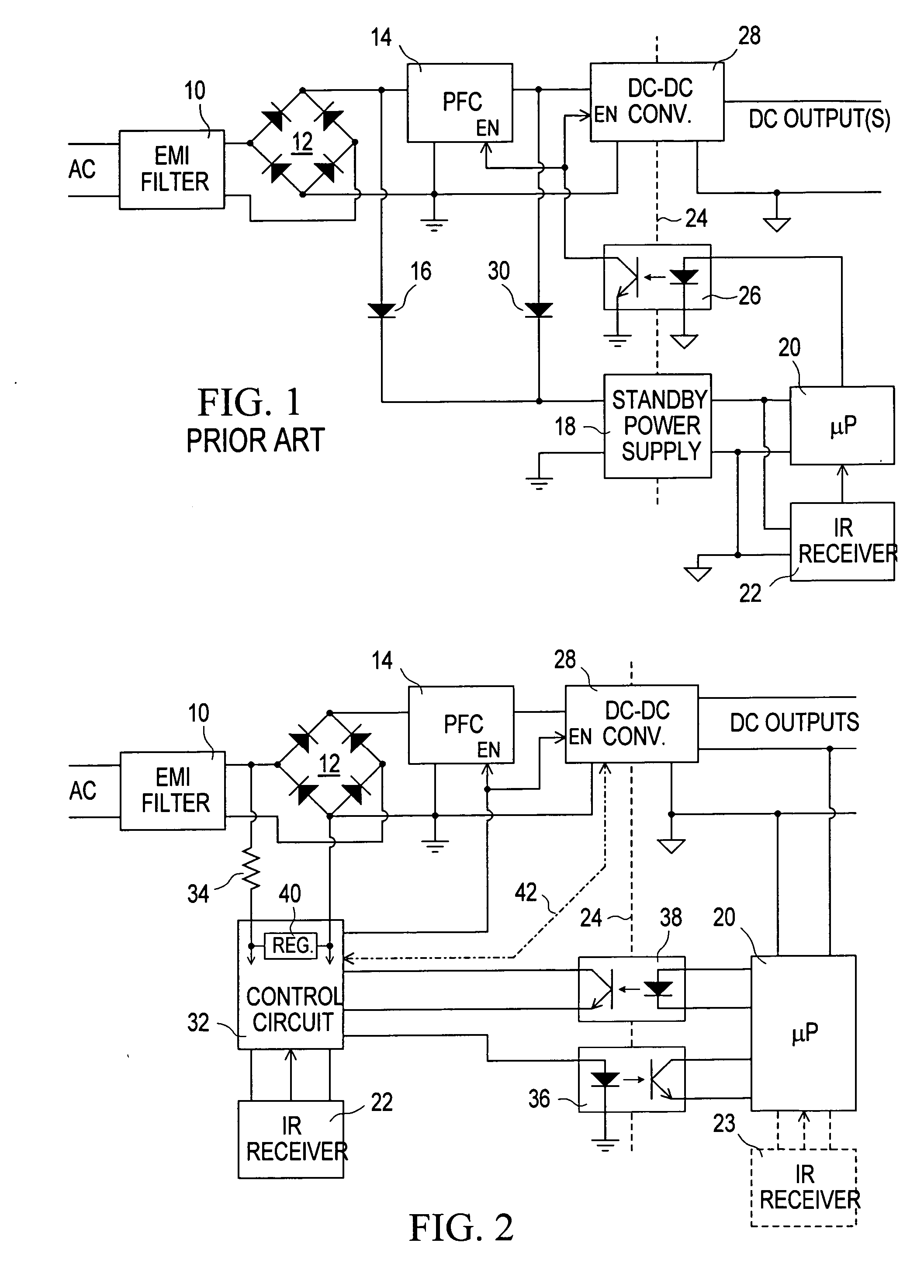
[0022] Referring to the drawings, FIG. 1 illustrates a known standby arrangement for a consumer electronics product, referred to below simply as a product. For example, the product may be a television receiver or other home entertainment equipment. The product has a standby mode as well as at least one normal operating mode.

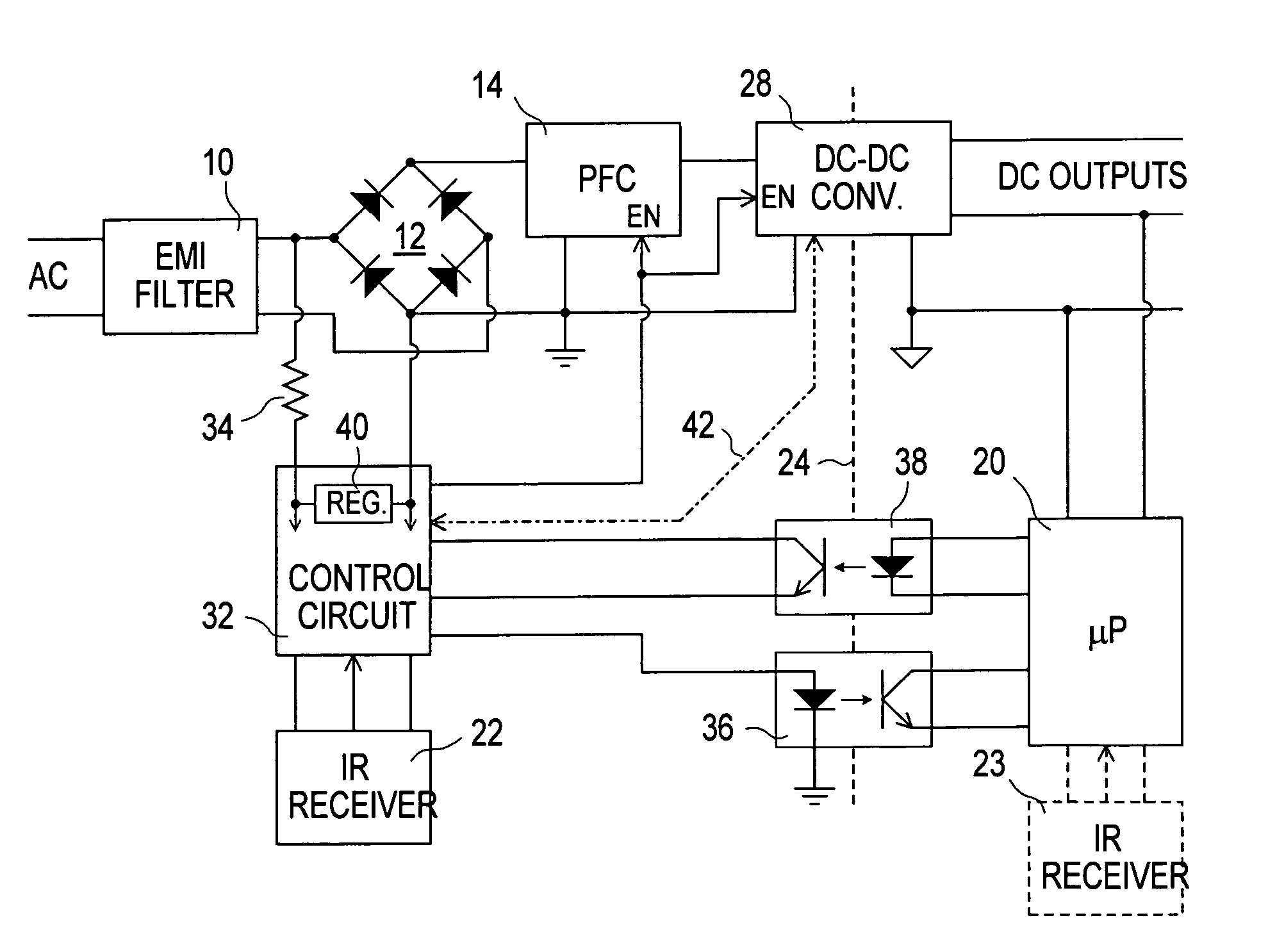
[0023] As shown in FIG. 1, an AC supply for the product is coupled via an EMI (electro-magnetic interference) filter 10 to a diode bridge rectifier 12, a DC output of which is coupled to a PFC (power factor correction) circuit 14 and via a diode 16 to a standby power supply 18. The standby power supply 18 may be a switch-mode converter which produces a regulated DC output constituting a power supply for a microprocessor (μP) 20 and an infrared (IR) signal receiver 22. The output of the standby power supply 18 is electrically isolated from the input, and hence from the AC supply, as shown by an isolation boundary represented by a dashed line 24.

[0024] The IR rec...


PUM


Abstract

An electronics product has a control unit responsive to a power-on remote control signal to enable DC power converters to supply power for normal operation of the product and to a microprocessor for responding to other remote control signals. The microprocessor controls the control unit to return to a standby mode of the product by disabling the DC power converters. The arrangement facilitates eliminating a conventional standby power supply and achieving a very low standby power consumption.

Description

[0001] This application claims the benefit of U.S. Provisional Application No. 60 / 740,241 filed Nov. 29, 2005, the entire contents and disclosure of which are hereby incorporated herein by reference.[0002] This invention relates to a standby arrangement for power supplies, for example for use in consumer electronics products such as televisions, home entertainment equipment and similar products with remote control receivers. BACKGROUND [0003] As is well known, many consumer electronics products include a remote control facility, typically using infrared communications but which may use radio frequency communications or other communications signals (including, for example, audio and ultrasonic signals), for use in controlling operation of the product. Such remote control generally includes an on / off control function, which is used to switch the product between a standby mode and a normal operating mode. [0004] In the standby mode, power must be supplied to those parts of the product ...

Claims


Application Information

Patent Timeline
Patent Type & Authority Applications(United States)
IPC IPC(8): G06F1/00
CPCY02B60/1282G06F1/3287G06F1/189Y02B60/1278G06F1/32Y02D10/00
Inventor ORR, RAYMOND K.
Owner POWER INTEGRATIONS INC
Why Eureka
Try Eureka