

Decoding device, decoding method, and receiving apparatus
- Summary
- Abstract
- Description
- Claims
- Application Information
AI Technical Summary
Benefits of technology
Problems solved by technology
Method used
Image

Examples
first embodiment
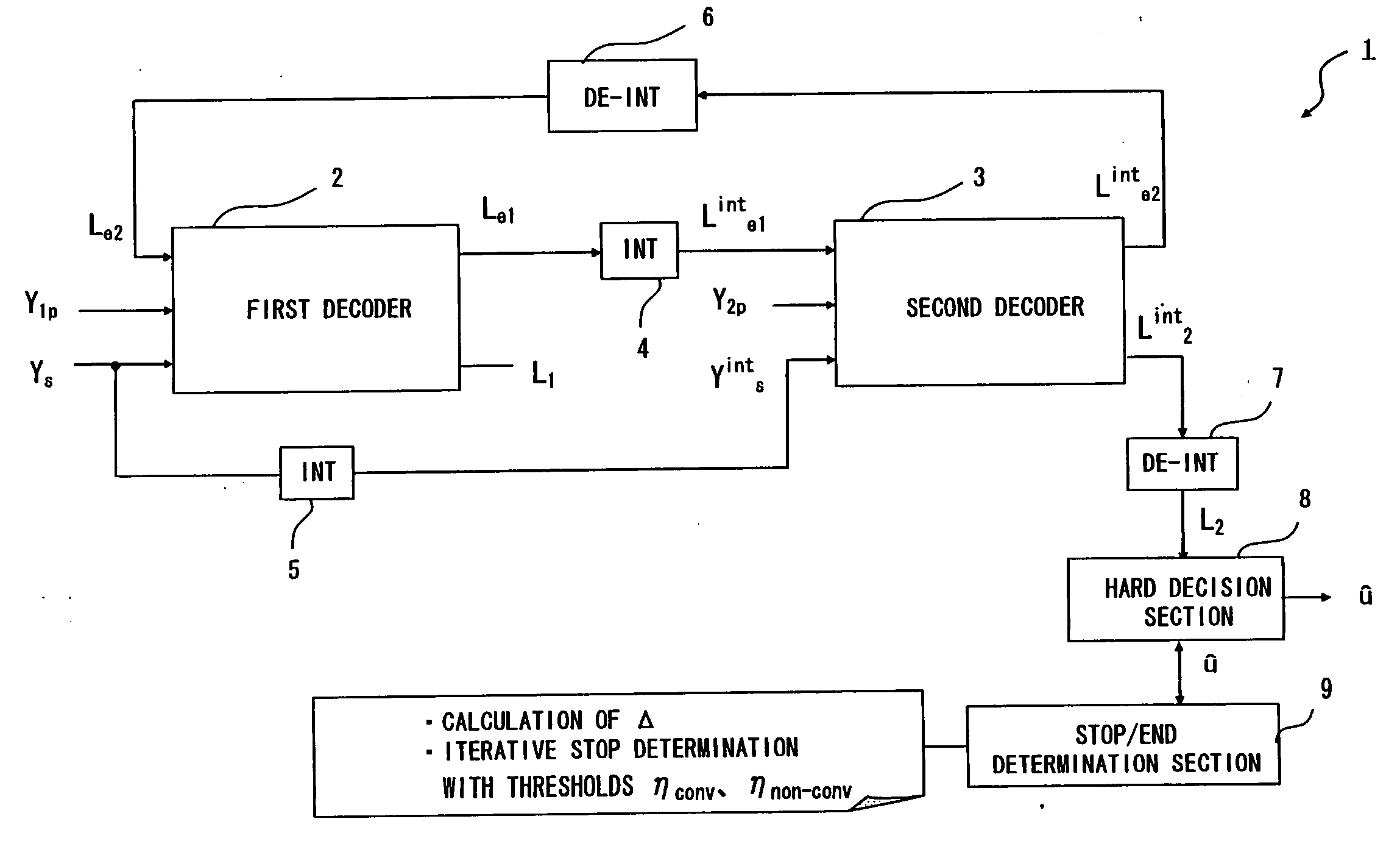
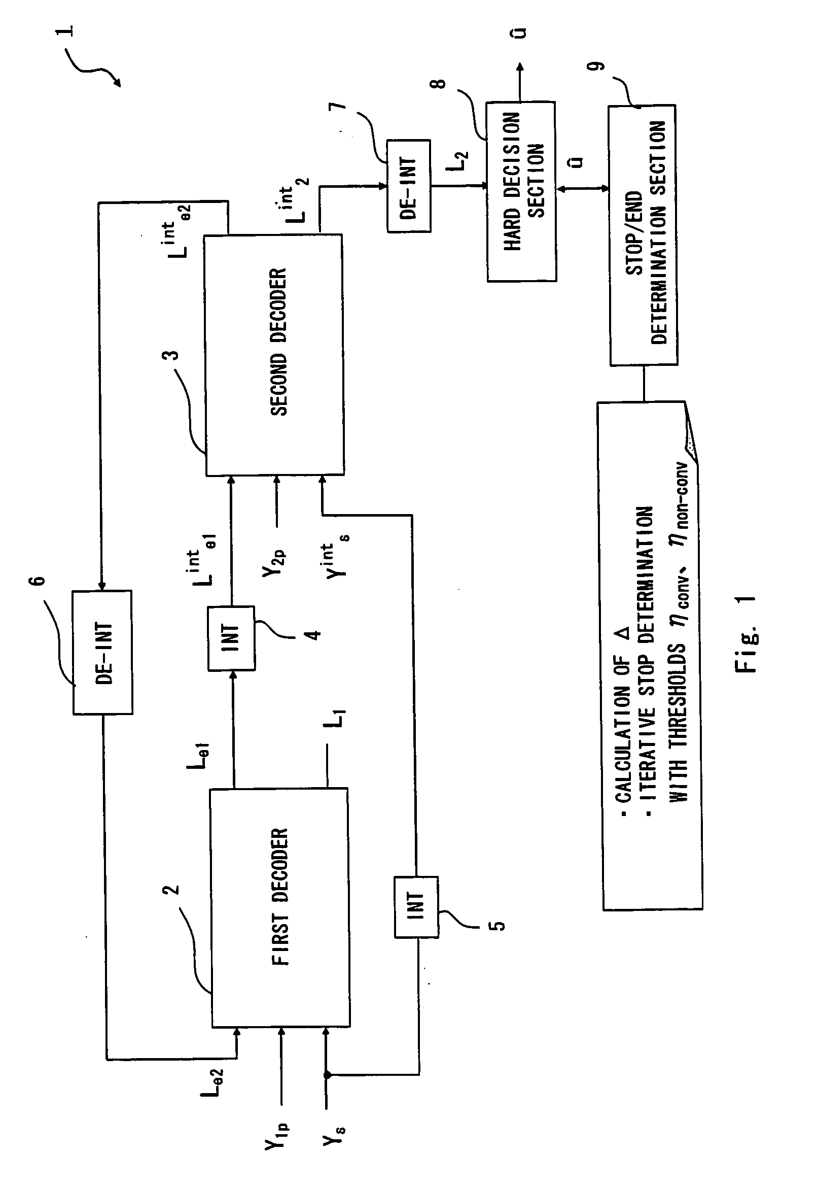
[0091]FIG. 1 is a view showing a decoding device 1 according to a first embodiment of the present invention. The decoding device 1 includes a first decoder 2, a second decoder 3, interleavers 4 and 5, de-interleavers 6 and 7, a hard decision section 8, and a stop / end determination section 9.
[0092] The decoding device 1 receives turbo codes as received data which are transmitted through a transmission line. The received data contains a first elemental code E and a second elemental code Eint which may be generated by an encoding device as shown in FIG. 12. The elemental codes E and Eint are composed of parity bits 1P, 2P and systematic bits U, Uint as described above. Because the systematic bits Uint of the second elemental code Eint can be obtained by interlaving the systematic bits U of the first elemental code E, the actually transmitted data are the systematic bits U and the parity bits 1P of the first elemental code E and the parity bits 2P of the second elemental code Eint. The...
second embodiment
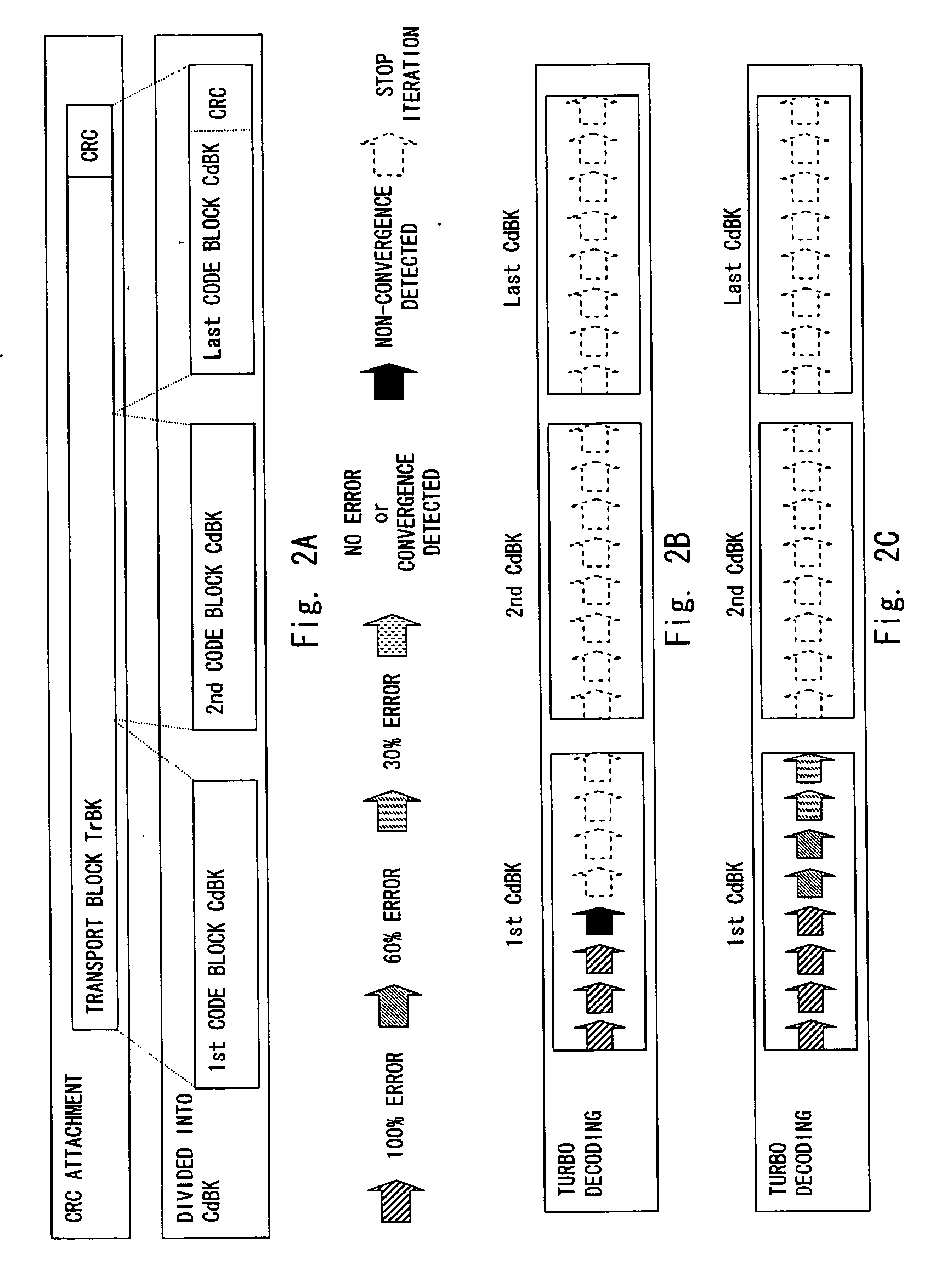
[0123] A second embodiment of the present invention is described hereinafter. This embodiment further increases the efficiency of the stop determination process in a code block which is performed as described in the first embodiment to thereby further reduce the number of times of iterative decoding. FIG. 6 is a view showing a decoding device according to this embodiment. In the second embodiment shown in FIG. 6 and an alternative embodiment of the second embodiment shown in FIG. 8 described later, the same elements as in the first embodiment shown in FIG. 1 are denoted by the same reference numerals and not described in detail herein.
[0124] As shown in FIG. 6, the second embodiment is different from the first embodiment in that the output of a first decoder 12 is supplied to the hard decision section 8. Specifically, in this embodiment, the first decoder 12 supplies the logarithmic likelihood ratio L1 which is generated in the process of decoding to the hard decision section 8. Th...
third embodiment
[0152] A third embodiment of the present invention is described hereinafter. A receiving apparatus according to this embodiment includes the decoding device according to the first or the second embodiment. FIG. 11 is a view showing the receiving apparatus which includes the above-described decoding device 1, 11 or 21. In addition to the decoding device 1,the receiving apparatus 40 further includes an antenna 41, an amplifier 42, an RF section 43, a demodulator 44, a de-puncturing section 45, a controller 46 for controlling these elements and so on as shown in FIG. 11.
[0153] In the receiving apparatus 40, the received data received by the antenna 41 is supplied to the amplifier 42. The amplifier 42 amplifies the received data and supplies the amplified data to the RF section 43. The RF section 43 performs high frequency processing such as high frequency conversion and supplies the processed received data to the demodulator 44 for demodulation. The demodulated received data is then s...
PUM
 Abstract
Description
Claims
Application Information