
Timing analyzer apparatus and timing analysis program recording medium

Inactive Publication Date: 2007-05-31
SOCIONEXT INC
View PDF3 Cites 7 Cited by
  • Summary
  • Abstract
  • Description
  • Claims
  • Application Information

AI Technical Summary

Benefits of technology

[0014] It is an object of the present invention to efficiently perform a timing analysis in designing a semiconductor integrated circuit, while reflecting the variations in cell delay more accurately.

Problems solved by technology

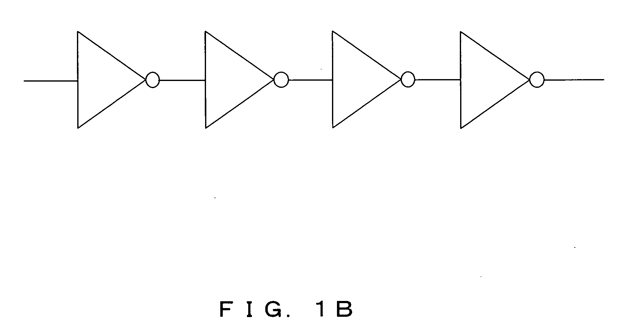
However, it is rare that only one gate circuit is present in an actual circuit, and therefore, timing verification in a case that a plurality of gate circuits are combined is required.
However, the above conventional timing analysis has the following problems.
In the timing verification in circuit designing, the variations of a plurality of the elements are simplified; however, the actual variations are not so simple as the variations in timing verification.
For that reason, the timing verification based on the estimation of the simplified variations, may cause an excess margin or an inadequate margin of the timing, incurring waste of motion or blocking circuit operation.
However, in recent years, types of cells employed for circuit designing are of great variety, and therefore the combinations of the cells become an enormous number.
Therefore, experimentally examining the correlation of all the combinations, or calculating the correlation of a number of paths by a computer involves a great deal of time, and it is not realistic.

Method used


Image

  • Timing analyzer apparatus and timing analysis program recording medium
  • Timing analyzer apparatus and timing analysis program recording medium
  • Timing analyzer apparatus and timing analysis program recording medium

Examples


Embodiment Construction

[0041] In the following description, details of the preferred embodiment of the present invention are set forth with reference to the drawings.

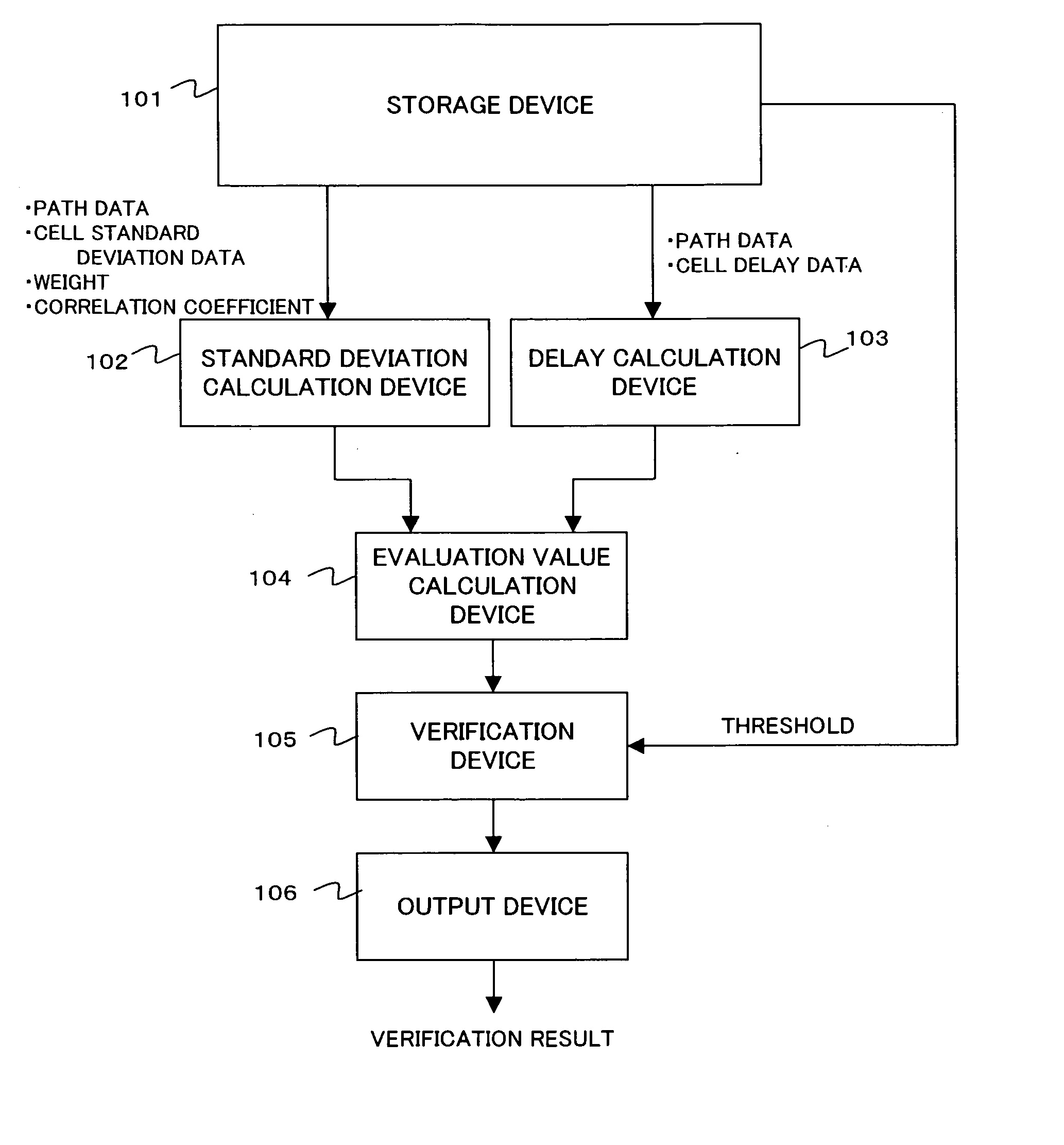
[0042]FIG. 2 is a diagram showing a principle of first and second timing analyzer apparatuses of the present invention. The timing analyzer apparatus shown in FIG. 2 comprises a storage device 101, a standard deviation calculation device 102, a delay calculation device 103, an evaluation value calculation device 104, a verification device 105, and an output device 106.

[0043] In the first timing analyzer apparatus, the storage device 101 stores a path data indicating a plurality of cells constituting a timing verification target circuit in a semiconductor integrated circuit, delay data and standard deviation data of each cell, a weight for calculating delay of standard deviation of the target circuit, and a threshold of the timing verification.

[0044] The standard deviation calculation device 102, using the path data and standard deviation d...


PUM


Abstract

By multiplying a square root of a sum of squares of a standard deviation of cells constituting a target circuit by a weight, or by calculating a square root of a sum of squares of a weighted standard deviation of the cells, the standard deviation of delay of the target circuit can be obtained. Using the obtained standard deviation of delay of the target circuit and the delay of the target circuit, timing verification is performed.

Description

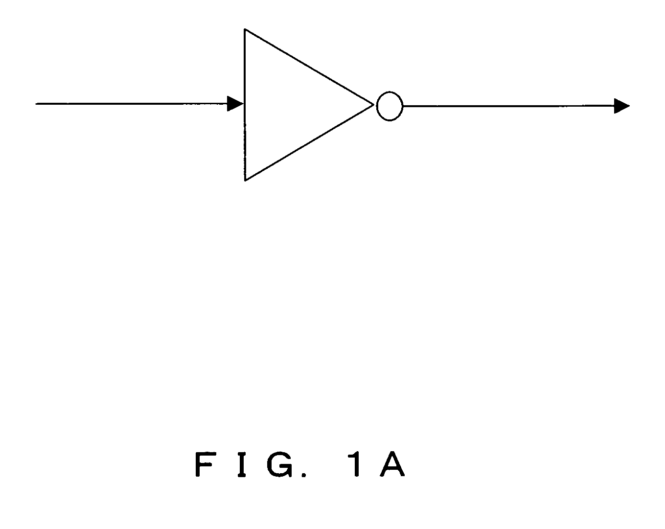
CROSS REFERENCE TO RELATED APPLICATIONS [0001] This application is based upon and claims the benefit of priority from the prior Japanese Patent Application No. 2005-343640, filed Nov. 29, 2005, the entire contents of which are incorporated herein by this reference. BACKGROUND OF THE INVENTION [0002] 1. Field of the Invention [0003] The present invention relates to an apparatus for performing a timing analysis of a circuit in designing a semiconductor integrated circuit and a program thereof. [0004] 2. Description of the Related Art [0005] A static timing analysis (STA), used in conventional semiconductor integrated circuit designing, verifies whether a circuit operates or not within a range between the maximum and the minimum delay values with variations, employing delay average value μ and standard deviation σ of a gate circuit, as shown in FIG. 1A. For example, in a case of a 3σ model, the timing verification is performed with in a range of the maximum value μ+3σ and the minimum v...

Claims


Application Information

Patent Timeline
IPC IPC(8): G06F17/50
CPCG06F17/5031G06F30/3312
Inventor SAKATA, TSUYOSHI
Owner SOCIONEXT INC
Learn More