Concave combustion chamber

Inactive Publication Date: 2007-06-07
CHRISWELL MR SHAWN D +1
View PDF30 Cites 5 Cited by
  • Summary
  • Abstract
  • Description
  • Claims
  • Application Information

AI Technical Summary

Benefits of technology

[0009] Another aspect of the present invention is to use a dual concave cylinder head to separate the fresh intake air from the burnt exhaust air, thereby reducing the inefficient exhaust of unburnt intake air during the exhaust cycle.
[0010] Another aspect of the present invention is to provide a reduced tim

Problems solved by technology

Nobody has invented a concave cylinder head which provides a strai

Method used


Image

  • Concave combustion chamber
  • Concave combustion chamber
  • Concave combustion chamber

Examples


Example

DETAILED DESCRIPTION OF THE DRAWINGS

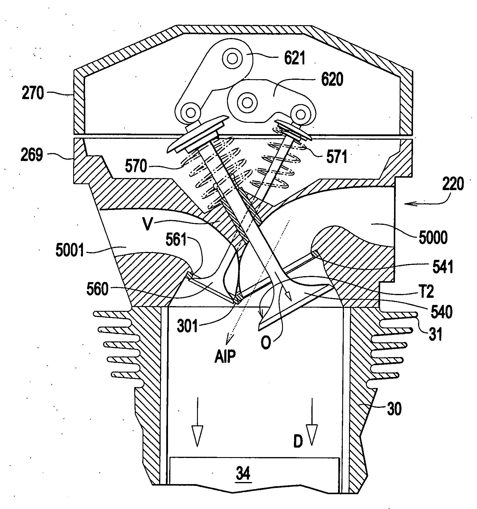
[0035] The term “concave” used herein means the cylinder head descends into the combustion chamber generally with a straight line segment that defines a wall that supports a valve.

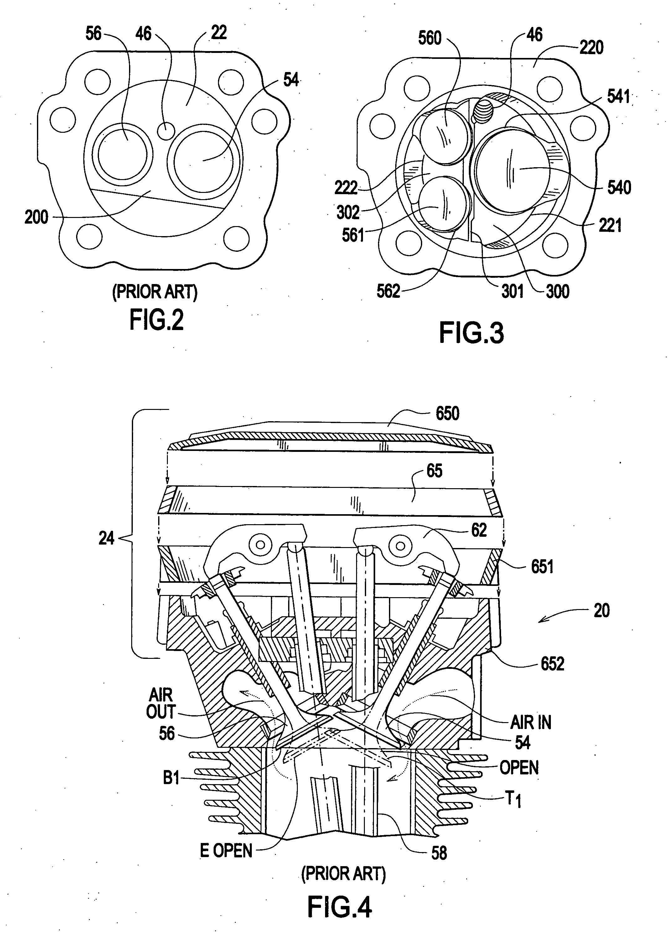
[0036] Referring first to FIGS. 1, 2, 4 there is a pushrod housing 68 for the pushrod 58.

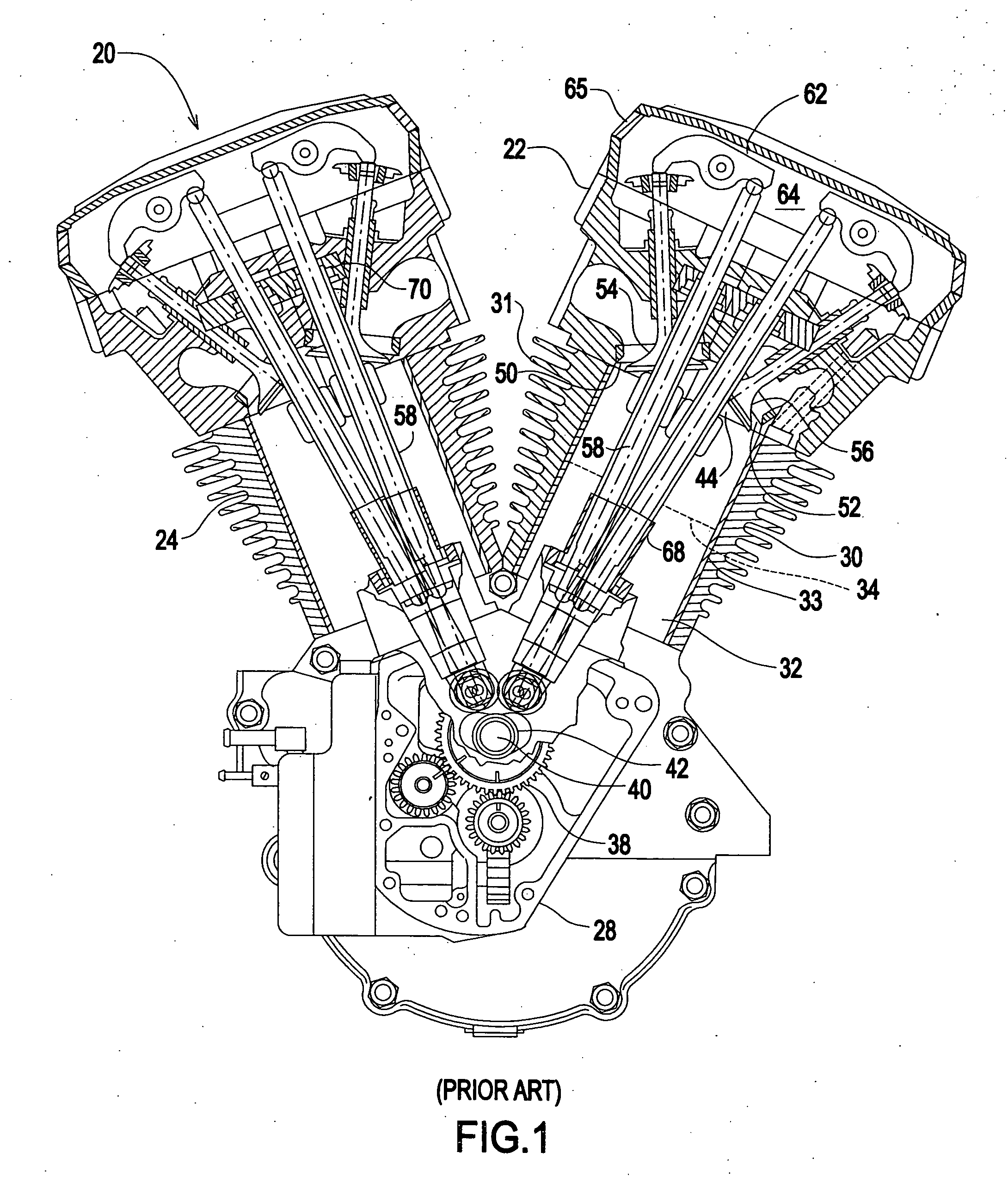
[0037]FIG. 1 is a side view illustration, in partial cross-section, of a V-twin motorcycle engine 20. The particular engine illustrated is the Stock '84-UP Big Twin motorcycle engine made by S&S Cycle, Inc. of Viola, Wis.

[0038] The V-twin motorcycle engine 20 is a two-cylinder engine. The two cylinders 24 and 26 are each attached to, and extend from, a single crank case 28. The two cylinders 24 and 26 are substantially identical, each having identical parts and operating in the same way. Each cylinder 24 and 26 includes a cylinder block 30, mounted to the crank case 28, and a cylinder head 22 mounted to the cylinder block 30. Both the cylinder head 22 and cylinder block 30 have f...


PUM


Abstract

An internal combustion engine is provided with a roughly concave cylinder head, wherein a ridge descends into the combustion chamber. A first wall is formed from the ridge to a cylinder periphery to form a seat for an air intake valve. A second wall is formed from the ridge to the opposite cylinder periphery to form a seat for one or more exhaust valves. The valves must criss-cross to open/close. The result is a more efficient flow of intake air and exhaust air to and from the combustion chamber which creates more horsepower. A plug compatible cylinder head can be installed on an engine to get added horsepower without a supercharger.

Description

FIELD OF INVENTION [0001] The present invention relates to improving performance of an internal combustion engine by means of shaping the cylinder head to more efficiently intake and exhaust the combustion air. BACKGROUND OF THE INVENTION [0002] Historically many types of combustion heads have been designed including flat heads, hemispherical (hemi-see Japanese Patent Pub. No. 52-54820, published May 4, 1977) and smoothed. The smoothed combustion chamber is disclosed in U.S. Pat. No. 5,941,221 (1999) to Marocco et al. His chamber is radiused and smoothed in order to reduce the surface area relative to the volume of the combustion chamber. His theory for improved efficiency is to increase the average combustion temperature, thereby producing more efficient combustion. [0003] Many efforts to improve engine efficiency (horsepower) by means of maximizing airflow velocity have been made. U.S. Pat. No. 6,691,661 (2004) to Lundgreen et al. discloses a tuned air induction apparatus for a V-...

Claims


Application Information

Patent Timeline
IPC IPC(8): F01L1/18
CPCF01L1/146F01L1/185F01L1/46F01L3/22F01L2001/0537F01L2003/255F01L2105/00F02F1/32F02F1/4285F02F2001/245F01L2305/00
Inventor CHRISWELL, SHAWN D.CHRISWELL, DARRELL R.
Owner CHRISWELL MR SHAWN D
Why Eureka
Try Eureka