Permanent chill mold for the continuous casting of metals

Inactive Publication Date: 2007-06-07
KME GERMANY GMBH & CO KG
View PDF2 Cites 10 Cited by
  • Summary
  • Abstract
  • Description
  • Claims
  • Application Information

AI Technical Summary

Benefits of technology

[0007] Accordingly, it is an object of the invention to set forth a permanent chill mold for the continuous casting of metals in which high casting speed at a desired billet quality may be run even when deviations from the operating point come about, and the shrinkage ratios of the metal inside the permanent chill mold change.

Problems solved by technology

When it comes to deviations from the predetermined operating point, the chosen geometry may lead to interference in the casting process and the billet quality, because on the billet, a so-called strand shell develops, as solidification of the molten metal in the casting bath level sets in.
In the case of inappropriate permanent chill mold geometry of the chill tube, the strand shell may lift off and rotate, or, in the opposite case, that is, at too little shrinkage, this may lead to great friction at the chill tube.
Bucking or jerking of the billet, billet spalling or even break-out may be the result.
The air gap between the chill tube and the strand shell also brings about irregular heat removal, the strand shell melts again with the result of external and internal cracks in the billet.
Although this design of the mold cavity represents the theoretically optimum geometry for a certain set of parameters, in practice there will still be parameter fluctuations, conditioned, for example, upon temperature control or upon changed steel compositions which make it impossible durably to maintain the predetermined operating point of the permanent chill mold.

Method used


Image

  • Permanent chill mold for the continuous casting of metals
  • Permanent chill mold for the continuous casting of metals
  • Permanent chill mold for the continuous casting of metals

Examples


Embodiment Construction

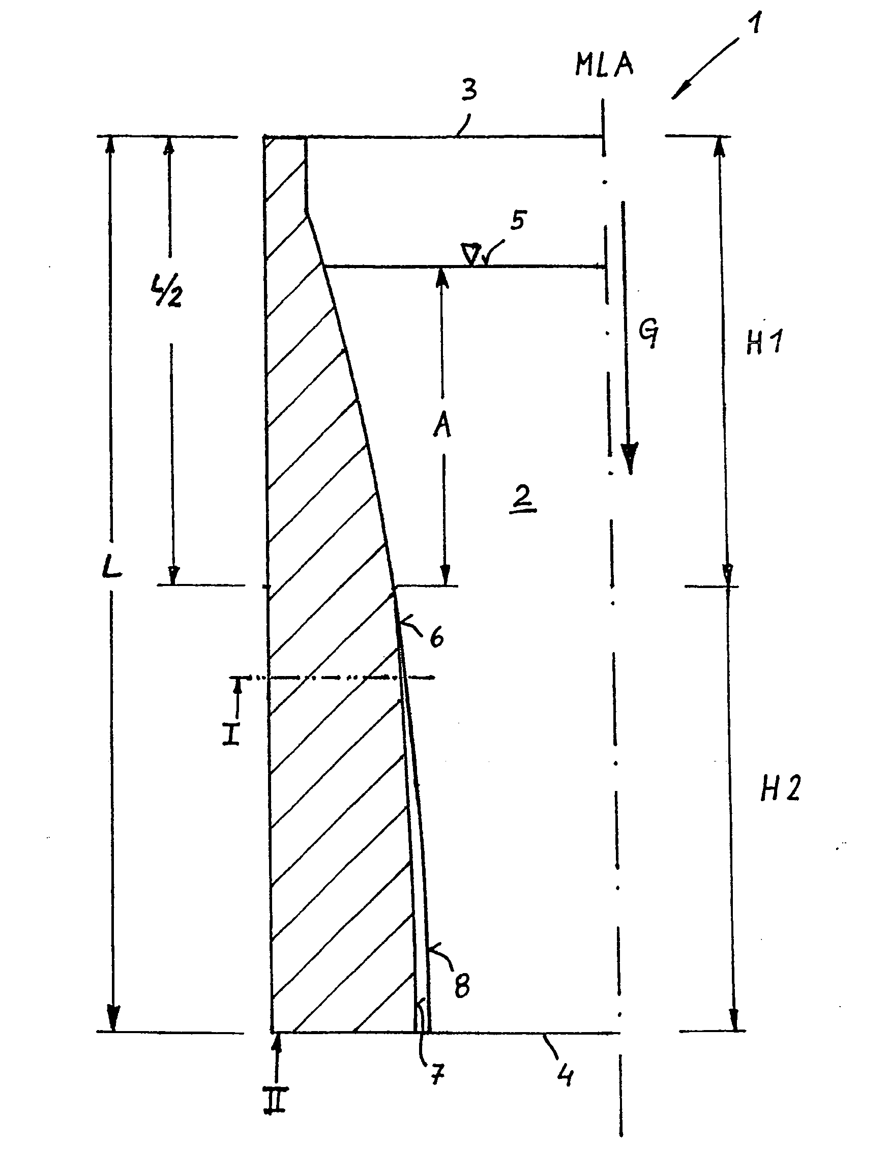
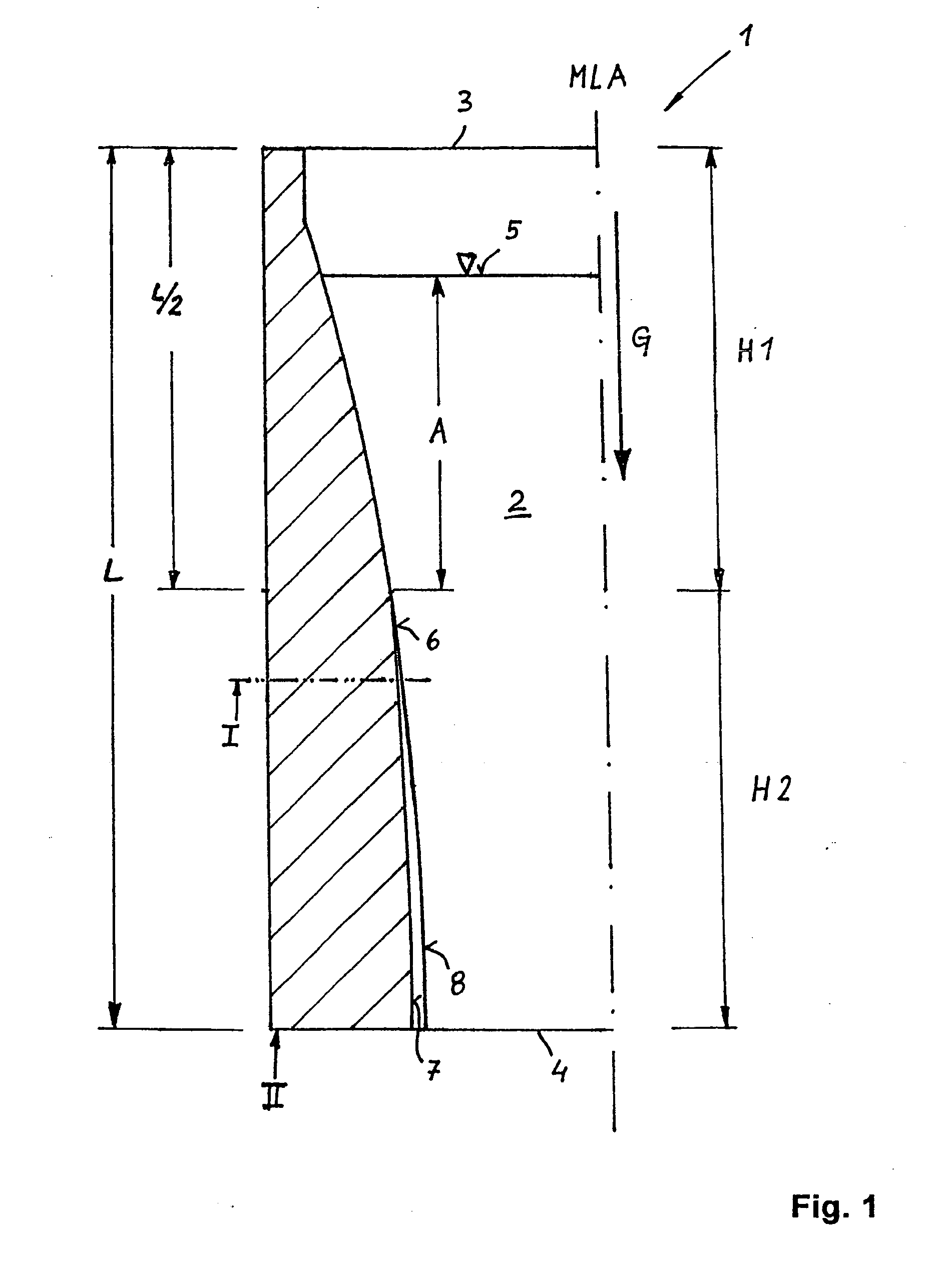
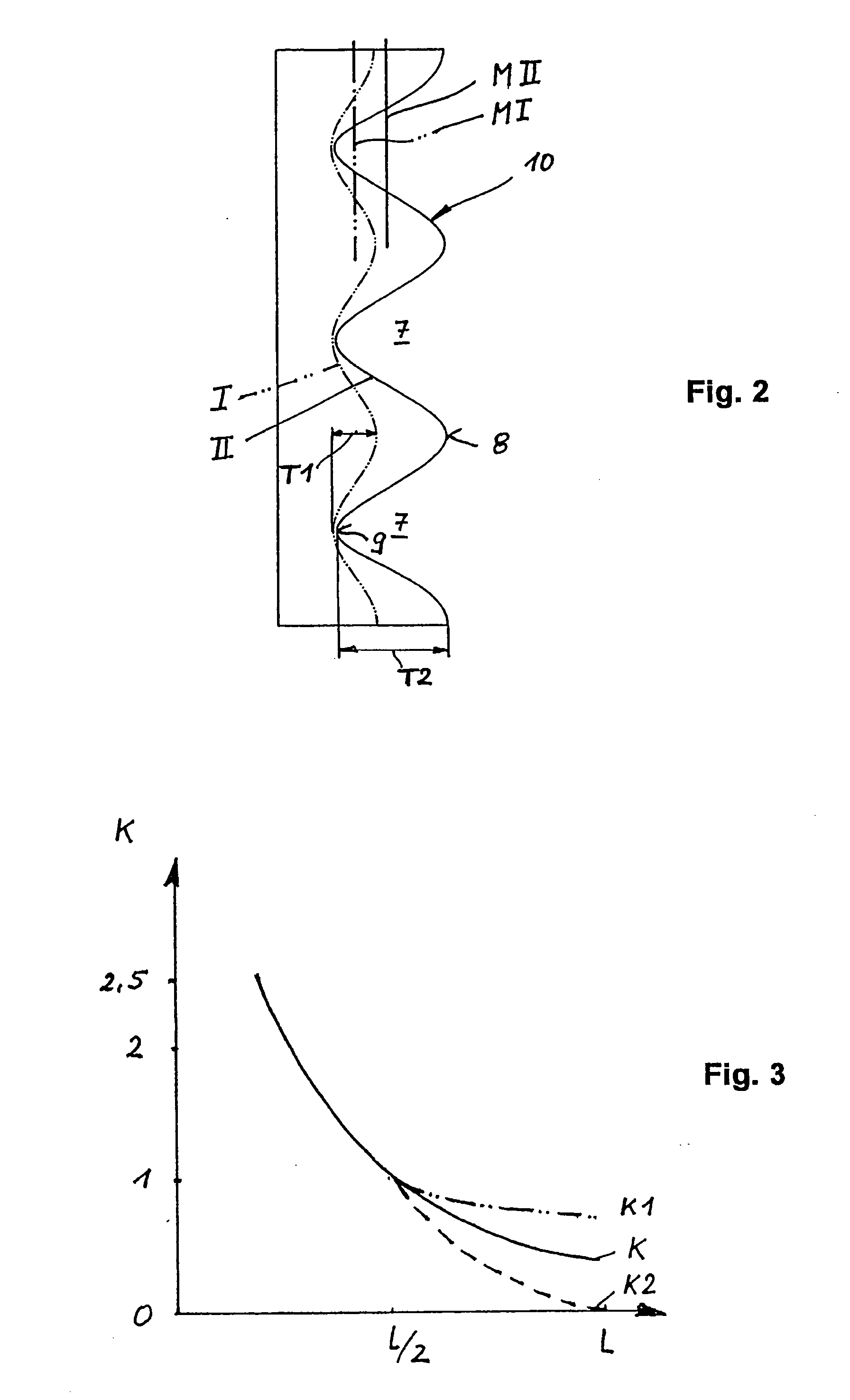
[0017] What is essential in the permanent chill mold according to the present invention is that at least one concave bulging or barrelling is provided that extends in the casting direction, which begins at a distance below a predetermined casting bath level position and extends up to the exit opening. Preferably, a plurality of bulgings is provided, so that in the lower height section of the permanent chill mold an undulated profiling, so to speak, comes about over the entire circumference or even only partial circumferential regions, in contrast to the straight side surfaces that occur in the normal case. The at least one concave bulging permits the strand shell of the solidified metal to position itself more or less greatly into the bulging provided for this, in response to deviations from the operating point. In this context, however, the strand shell is securely guided at all times, so that, for example, a twisting or a shaping in a rhomboid fashion of the strand shell is able t...


PUM

PropertyMeasurementUnit
Fractionaaaaaaaaaa
Fractionaaaaaaaaaa
Fractionaaaaaaaaaa

Abstract

A permanent chill mold for the continuous casting of metal, having a mold cavity (2) which has a pouring slot (3), an exit opening (4) and a casting cone (6). At least one concave bulging (7) is provided that extends in the casting direction (G), which begins at a distance (A) below a predetermined casting bath level position (5) and extends up to the exit opening (4).

Description

BACKGROUND OF THE INVENTION [0001] 1. Field of the Invention [0002] The invention generally relates to a permanent chill mold for the continuous casting of metals. [0003] 2. Description of Related Art [0004] Tube-shaped chill molds made of copper or copper alloys, for casting profiles made of steel or other metals having a high melting point have been described many times in the related art. Permanent chill tubes usually have a uniform wall thickness in a horizontal cross sectional plane, which increases in the direction of the billet because of the inner conicity or taper of the chill tube. The conicity is able to be the same over the entire length of the permanent chill mold. However, conicities that are variable over the length may also be used, and the conicity may be greater especially in the region of the pouring slot, and may decrease in the casting direction, in order to be able to follow especially well the shrinkage of the cast billet in response to cooling, and thereby as...

Claims


Application Information

Patent Timeline
IPC IPC(8): B22D11/00
CPCB22D11/04B22D11/0406B22D11/041B22D11/043B22D17/00C22C9/00
Inventor WOBER, HANS-GUNTERHUGENSCHUTT, GERHARDKOLBECK, DIETMARBOLDT, RAIMUNDMAIWALD, FRANKREINELT, DANIELPIWOWAR, HANS-DIRKRODE, DIRK
Owner KME GERMANY GMBH & CO KG
Why Eureka
Try Eureka