Method of making aluminum alloy plate for bearing

Inactive Publication Date: 2002-08-27
DAIDO METAL CO LTD
View PDF6 Cites 5 Cited by
  • Summary
  • Abstract
  • Description
  • Claims
  • Application Information

AI Technical Summary

Problems solved by technology

However, the bearing aluminum alloy of hard Al--Sn--Si system or Al--Sn--Si--Mn system has a low rolling workability of the aluminum alloy.
Accordingly, there is a possibility that crack may occur when the bonding layer is cladded onto the bearing alloy layer.
However, the Al--Sn--Si alloy or Al--Sn--Si--Mn alloy, each of which serves as the bearing alloy layer and has a low rolling workability, cannot withstand pressurization or cladding at such a high reduction ratio as mentioned above in order that occurrence of crack may be prevented for increase in the yield.
Accordingly, since the bonding layer is cladded onto each layer of these bearing alloys at a low reduction ratio, the bonding strength between the bearing alloy layer and the bonding layer becomes insufficient.
However, the conventional belt casting machines have low cooling rates such that a cast plate is gradually cooled.
As a result, since crystals become easy to coarsen or segregate, the rolling workability and bearing characteristic are deteriorated.
However, since the machine carries out the belt casting method although being provided with the water sprayer, the casting speed becomes high but the cooling rate becomes low.
Accordingly, it is difficult to completely prevent the crystals from being coarsened.
Thus, the bearing alloy plate made by the belt casting machine with the water sprayer fairly improves a rolling workability but is still difficult to roll.
Particularly when the plate contains Si,

Method used


Image

  • Method of making aluminum alloy plate for bearing
  • Method of making aluminum alloy plate for bearing
  • Method of making aluminum alloy plate for bearing

Examples


Embodiment Construction

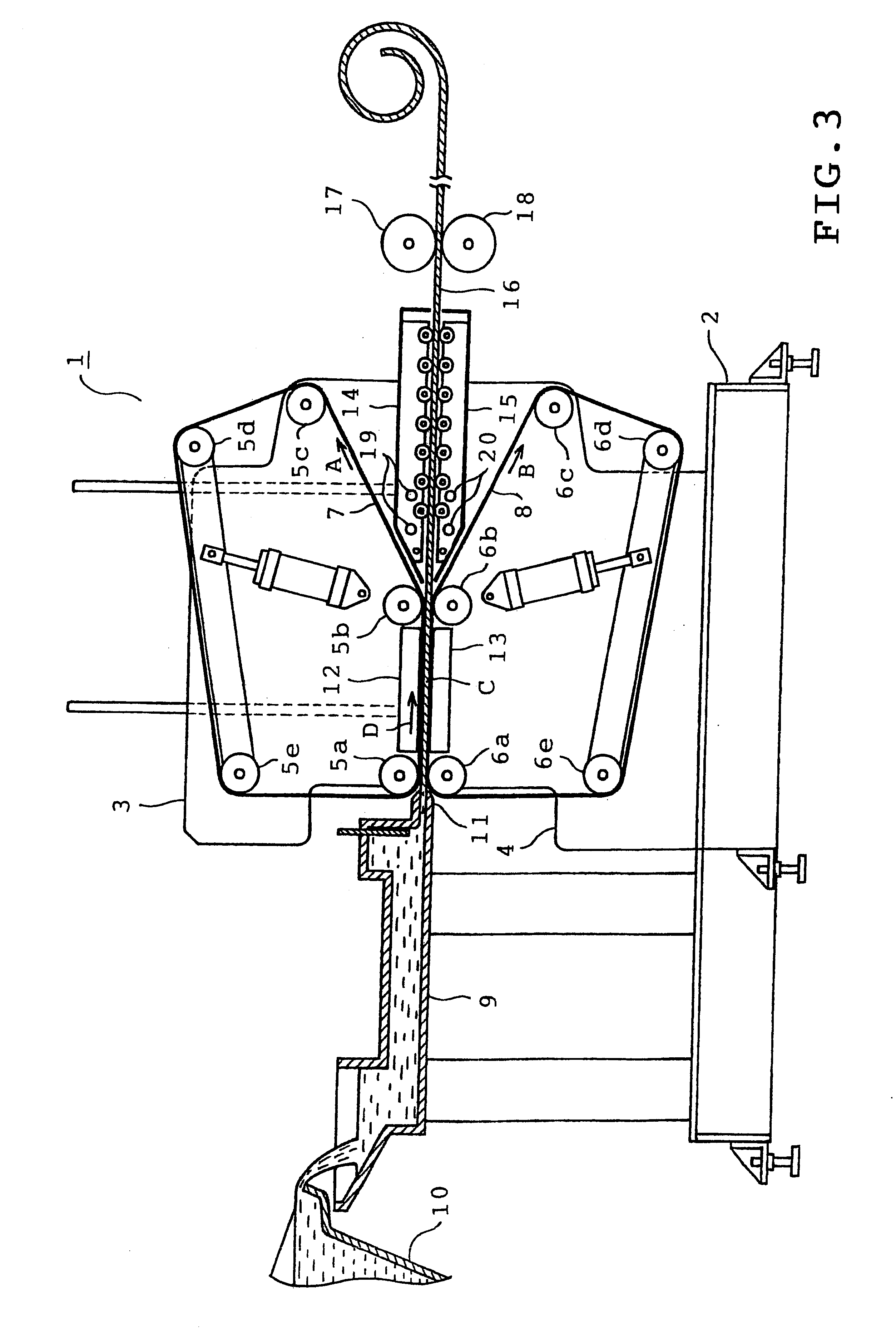
One embodiment of the present invention will be described with reference to the accompanying drawings. Referring first to FIG. 3, a belt casting machine 1 is shown which casts an aluminum bearing alloy into the shape of a plate. The belt casting machine 1 comprises a base 2 and a pair of upper and lower machine frames 3 and 4. A plurality of rollers 5a to 5e and 6a to 6e are mounted on the frames 3 and 4 respectively. A pair of endless belts 7 and 8 are passed through the rollers 5a-5e and 6a-6e respectively. Each endless belt is made of a steel plate or heat-resistant fiber.

The rollers 5a-5e and 6a-6e are coupled to respective electric motors (not shown). Upon drive of the motors, the belts 7 and 8 are driven so as to travel in the directions of arrows A and B respectively. A part of the upper endless belt 7 between the rollers 5a and 5b is substantially parallel to a part of the lower endless belt 8 between the rollers 6a and 6b. A space where the belts 7 and 8 are parallel to eac...


PUM

PropertyMeasurementUnit
Fractionaaaaaaaaaa
Fractionaaaaaaaaaa
Fractionaaaaaaaaaa

Abstract

A method of making an aluminum alloy plate for bearing which is made by cladding a bonding layer comprising a pure aluminum or an aluminum alloy excluding Sn onto a bearing alloy layer comprising an aluminum alloy containing Sn. The method includes the steps of fitting a concave portion of a first roll in a convex portion of a second roll, the first roll having both axial ends with large diameter portions respectively, the second roll having both axial ends with small diameter portions respectively, and passing superposed plates formed into the bearing alloy layer and the bonding layer respectively through a roll gap defined between the concave and convex portions and closed by the large diameter portions of the first roll so that the plates are rolled down at a reduction ratio not less than 50% while both widthwise ends of each plate is restricted by the large diameter portions of the first roll respectively such that the bonding layer is cladded onto the bearing alloy layer.

Description

1. Field of the InventionThis invention relates to a method of making an aluminum alloy plate for bearing by cladding a bonding layer comprising a pure aluminum or an aluminum alloy excluding Sn onto a bearing alloy layer comprising an aluminum alloy.2. Description of the Prior ArtIn making a bearing lined with an aluminum alloy (aluminum alloy bearing), a bearing alloy layer comprising an aluminum alloy containing Sn is generally bonded to a back metal with a bonding layer being interposed therebetween, so that a bimetal is made. The bonding layer comprises a pure aluminum or an aluminum alloy. The bimetal is then machined into an aluminum alloy bearing. The bonding layer is bonded to the bearing alloy layer prior to bonding of the bearing alloy layer to the back metal. The bonding layer is cladded onto the bearing alloy layer when bonded thereto. More specifically, a plate formed into the bearing alloy layer and a plate formed into the bonding layer are passed between a pair of fl...

Claims


Application Information

Patent Timeline
IPC IPC(8): B32B15/01F16C33/12F16C33/04F16C17/02B22D11/00B22D11/06B23K20/04B23K103/10C22C21/00F16C9/02F16C9/04F16C33/14
CPCB22D11/008C22C21/003C22C21/02F16C33/121B32B15/016B21B31/07B21B2003/001Y10T29/302B23K20/04
Inventor KAGOHARA, YUKIHIKOFUJITA, MASAHITOYAMAMOTO, KOICHISHIBAYAMA, TAKAYUKI
Owner DAIDO METAL CO LTD
Why Eureka
Try Eureka