Tubular mould for continuous casting

a technology of continuous casting and tubular moulds, which is applied in the direction of permanent magnets, electromagnets, etc., can solve the problems that the service life of the moulds also constitutes an important cost factor for the economic efficiency of the continuous casting plant, and achieve the effect of preventing electrolytic corrosion

Active Publication Date: 2008-09-09
CONCAST AG
View PDF8 Cites 4 Cited by
  • Summary
  • Abstract
  • Description
  • Claims
  • Application Information

AI Technical Summary

Benefits of technology

[0020]If the supporting plates are produced from a metallic material, it is advantageous to prevent the electrolytic corrosion due the cooling water by a protective layer arranged between the supporting plates and the copper tube. Such a protective layer can be constructed, for example, by a copperplating of the supporting plate. It is however also possible to close off the cooling ducts let into the copper tube with a copper layer produced by electrodeposition.
[0021]The cooling ducts in the copper tube are connected to water supply and discharge lines at the supporting plates or at the supporting shell. According to an exemplary embodiment, it is advantageous for the water supply and discharge lines to be arranged alongside each other on the supporting plates at the upper end of the mould and to be connectable to the cooling-water system by means of a quick coupling.

Problems solved by technology

However, besides the cooling capacity, which may exert a direct influence on the output per strand for a given strand format, the service life of the mould also constitutes an important cost factor for the economic efficiency of the continuous casting plant.

Method used


Image

  • Tubular mould for continuous casting
  • Tubular mould for continuous casting
  • Tubular mould for continuous casting

Examples


Embodiment Construction

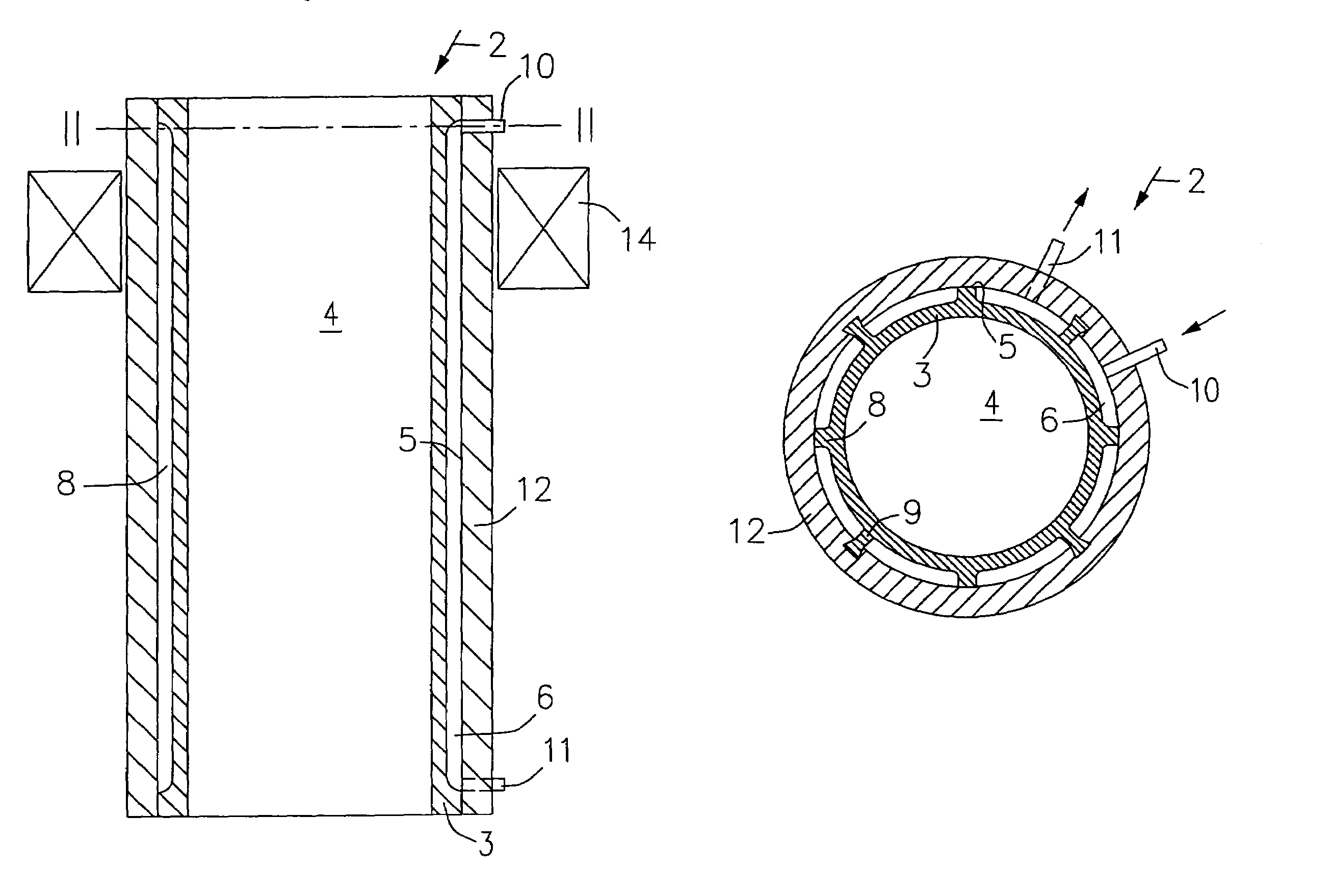
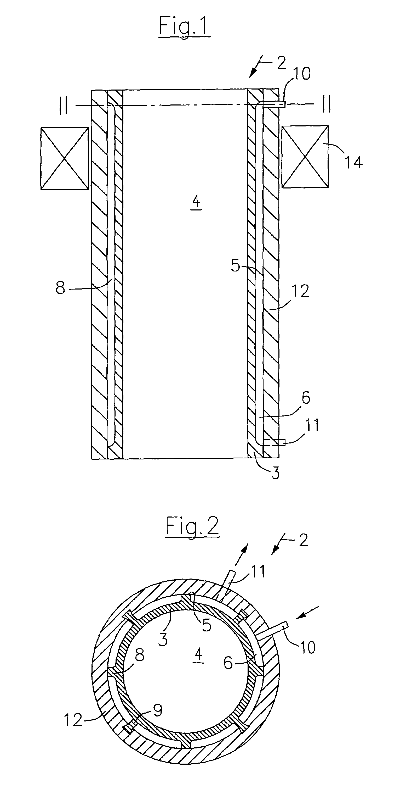
[0030]In FIGS. 1 and 2, a continuous casting mould for round billet or bloom strands is depicted by 2. A copper tube 3 forms a mould cavity 4. Provided at the outer side of the copper tube 3, which side forms the tube outer lateral surface 5, is water-circulation cooling for the copper tube 3. This water-circulation cooling comprises cooling ducts 6 distributed over the entire circumference and substantially over the entire length of the copper tube 3. The individual cooling ducts 6 are delimited by supporting and connecting ribs 8 and 9, respectively, an additional task of which is to guide the cooling-water circulation into the cooling ducts 6 from a water supply line 10 to a water discharge line 11. 12 depicts a supporting shell which surrounds the copper tube 3 over the entire circumference and over the entire length and supports the copper tube 3 at the tube outer lateral surface 5 via the supporting ribs 8. The connecting ribs 9 connect the copper tube 3 to the supporting shel...


PUM

PropertyMeasurementUnit
thicknessaaaaaaaaaa
thicknessaaaaaaaaaa
thicknessaaaaaaaaaa

Abstract

In the continuous casting of round or polygonal billet and bloom formats, use is made of moulds the mould cavity of which comprises a copper tube (3) which is intensively cooled by means of water-circulation cooling. In order to increase the cooling capacity on the one hand and the dimensional stability of the mould cavity (4) on the other hand, and also extend the total service life of the copper tube (3), it is proposed to provide the copper tube (3) with a supporting shell (12) or supporting plates over the entire circumference at the tube outer lateral surface (5). For the cooling of the copper tube (3), cooling ducts (6) for guiding the cooling water are arranged on the copper tube (3) or on the supporting shell (12). The cooling ducts (6) are distributed over the entire circumference at the tube outer lateral surface (5) and extend substantially over the entire mould length.

Description

CROSS REFERENCE TO PRIOR APPLICATION[0001]This is a U.S. national phase application under 35 U.S.C. §371 of International Patent Application No. PCT / EP2004 / 003712, filed Apr. 7, 2004, and claims benefit of European Patent Application No. 03008681.3, filed Apr. 16, 2003, which is incorporated by reference herein. The International Application was published in German on Oct. 28, 2004 as WO 2004 / 091826 A1 under PCT Article 21(2).BACKGROUND OF THE INVENTION[0002]1. Field of the Invention[0003]The invention relates to a tubular mould for the continuous casting of round and polygonal billet and bloom cross-sections according to the precharacterising clause of claim 1 or 2.[0004]2. Description of Related Art[0005]In the continuous casting of steel in billet and small bloom cross-sections, tubular moulds are used. Such tubular moulds comprise a copper tube fitted into a water jacket. In order to achieve circulation cooling with a high flow rate of the cooling water, a tubular displacer is a...

Claims


Application Information

Patent Timeline
Patent Type & Authority Patents(United States)
IPC IPC(8): B22D11/055B22D11/00B22D11/04
CPCB22D11/00B22D11/055B22D11/04B22D11/115B22D11/124H01F7/02H01F7/06
Inventor ROEHRIG, ADALBERTKAWA, FRANZ
Owner CONCAST AG
Why Eureka
Try Eureka