Temperature-sensing device

a temperature sensor and temperature technology, applied in the direction of resistor details, heat measurement, instruments, etc., can solve the problems of corrosion, affecting so as to prevent the electrolytic corrosion and improve the anti-corrosion effect of the temperature sensor

Inactive Publication Date: 2007-01-25
HITACHI LTD
View PDF4 Cites 7 Cited by
  • Summary
  • Abstract
  • Description
  • Claims
  • Application Information

AI Technical Summary

Benefits of technology

[0011] The problem to be solved by the present invention is how to improve the anti-corrosion of a temperature sensor mounted on an automobile such as a thermistor in which electrolytic corrosion easily occurs due to adhesion of water or salt water. The electrolytic corrosion in a temperature-sensing device such as a temperature sensor and a temperature-sensitive resistor provided by the present invention is a phenomenon in which a liquid containing a conductive material such as ions adheres to the surface of an insulating coat of the device, and then, as the adhering amount increases to connect lead wires, an electrochemical cell is formed at the connection between the lead wire and an electrode and corrodes the connection between the lead wire and the electrode or its vicinities. Thus, in order to prevent the electrolytic corrosion, it is necessary to avoid the liquid containing ions from adhering to or remaining on the surface of the insulating coat to eliminate electric connection between the lead wires.

Problems solved by technology

Therefore, if salt water adheres to the exposed welded part, corrosion may occur.
However, the plating is porous microscopically and the basis material is often exposed partially.
Since it is difficult to form a complete coat with the plating, it cannot be said that the perfect anti-corrosion structure is provided.
When the leads are bridged with the salt water, a leakage of current may cause an error in temperature measurement and electrolytic corrosion.
It cannot be said that the use of the epoxy resin is an effective approach to prevent the abovementioned electrolytic corrosion due to the adhesion of the salt water since the epoxy resin has no hydrophobic group in its molecular structure and does not easily repel salt water adhering to the epoxy resin.

Method used


Image

  • Temperature-sensing device
  • Temperature-sensing device
  • Temperature-sensing device

Examples


example 1

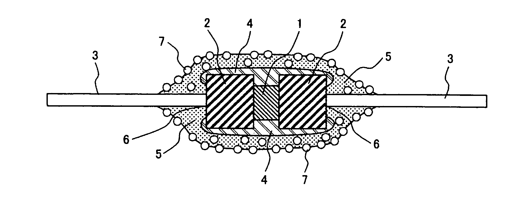
[0056] First, the problems of a conventional temperature sensor will be described with reference to FIG. 9. FIG. 9 shows the sectional structure of a conventional thermistor (a temperature sensor) using a thermistor chip commonly called as an axial type. FIG. 1 is a section view of a thermistor according to the present invention.

[0057] The structure of the temperature sensor according to the present invention using the thermistor chip will be described with reference to FIG. 9. Reference numeral 1 shows the thermistor chip formed of a semiconductor having properties (such as a resistance value) which vary with a temperature change. Electrodes (not shown) for detecting signals are provided on both ends of the thermistor chip 1. A sealing electrode 2 is connected to each of the electrodes on both ends of the thermistor chip 1 in the way electrical conductivity is not lost.

[0058] The sealing electrode 2 is often formed of dumet which has cuprous oxide (Cu2O) including copper as an in...

example 2

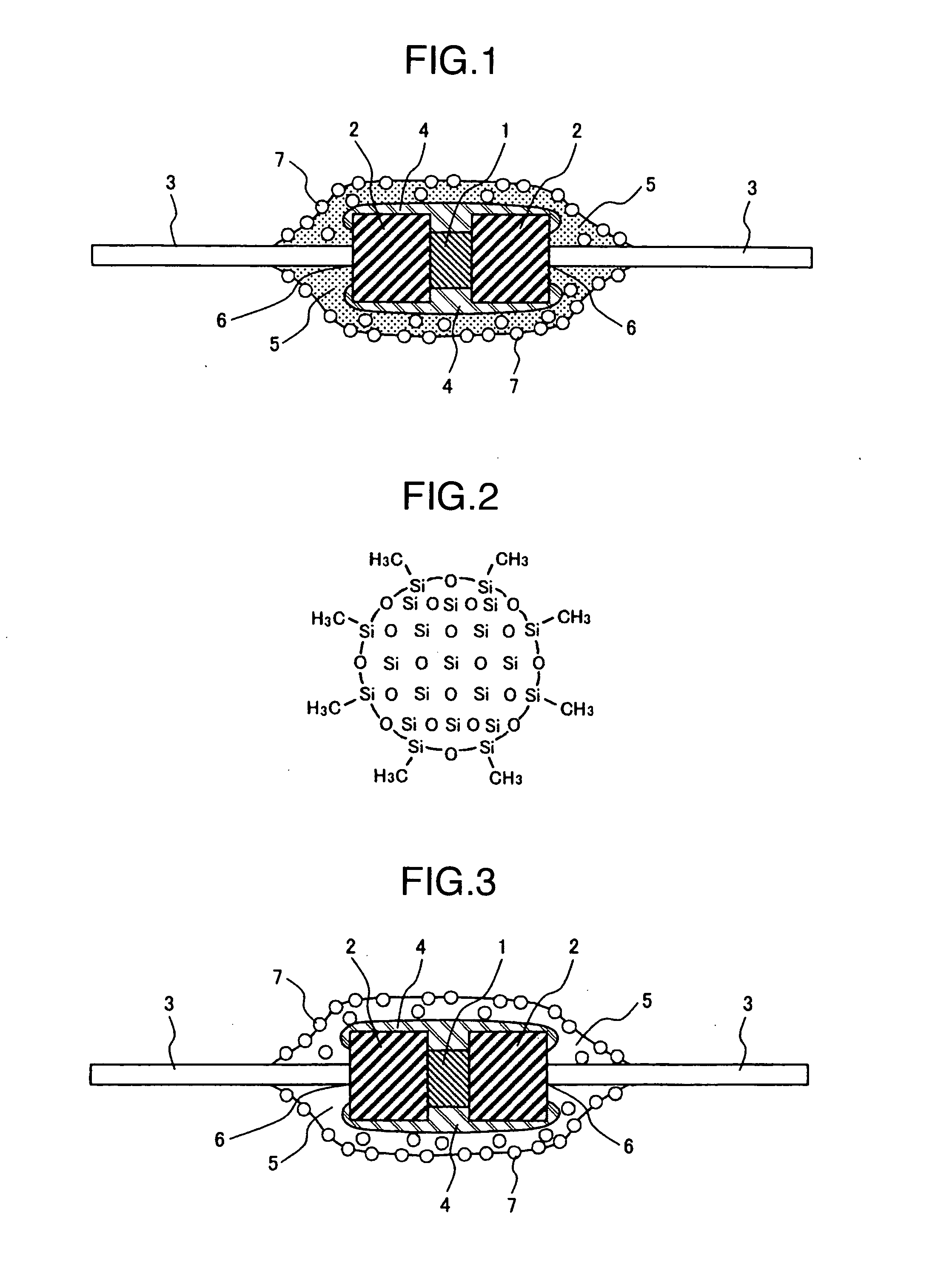
[0078]FIG. 3 shows Example 2 different from Example 1 shown in FIG. 1. Example 2 provides a structure for further improving the effect of hydrophobicity on the surface caused by the hydrophobic fillers contained in the resin member. The axial-type thermistor shown in FIG. 9 is used as the structure of the thermistor of Example 2. The thermistor coated with a resin 5 is further covered with a resin containing fillers having hydrophobic groups as a second layer coat film 8 on the surface of a first layer coat film 7. An example of an epoxy resin used as the coat member 5 will be described. The thermistor is coated with the epoxy resin as the first layer coat film 7.

[0079] The epoxy resin is volatilized with a solvent at a temperature before the ring is opened in provisional drying (semi-curing). The surface of the coat after the provisional drying is coated with an epoxy resin of at least 5 wt % as the second layer coat film 8 provided by appropriately adding hydrophobic fillers to t...

example 3

[0080] Another method for realizing Example 1 shown in FIG. 1 will be described. After the entire glass tube 4 including the welded part 6 between the lead wire 3 and the sealing electrode 2 of the thermistor is coated with the resin 5, the solvent is vaporized at a temperature before the epoxy ring is opened, that is, provisional drying is performed. In that state, hydrophobic fillers are caused to adhere to the surface of the resin coat 5 and then main drying is performed. In this manner, the surface can be reformed to have water repellency.


PUM

PropertyMeasurementUnit
particle sizeaaaaaaaaaa

Abstract

A temperature-sensing device includes an element with a resistance value varying with a temperature change, a lead extending on the axis of the element, and a resin coat surrounding the element, wherein a number of hydrophobic inorganic fillers with an average particle size of 5 μm or less exist on a surface of the resin coat. The temperature sensor may have a sealing electrode electrically connected to each end of the element, the lead being electrically connected to each of the sealing electrodes and extending on the axis direction of a composite body formed of the element and the sealing electrode, and an inorganic insulating member surrounding the element and covering at least part of the sealing electrodes, the resin coat covering at least a connecting portion between the electrode and the lead wire.

Description

FIELD OF THE INVENTION [0001] The present invention relates to a temperature-sensing device which is an electronic component such as a temperature sensor and a temperature-sensitive resistor, and more particularly, to an electronic component such as a temperature-sensing device with high resistance to corrosion suitable for use as a temperature sensor having lead wire which measures the temperature of intake air in an automobile and which is used in an environment where the component is susceptible to corrosion and electrolytic corrosion. [0002] Thus, the present invention technically relates to a device having the function of changing a resistance value with a temperature change, for example, a temperature sensor and a temperature-sensitive resistor device. BACKGROUND OF THE INVENTION [0003] Many temperature sensors, which are thermistors using a device having the function of changing physical properties such as a resistance value with a temperature change, have been used in consum...

Claims


Application Information

Patent Timeline
Patent Type & Authority Applications(United States)
IPC IPC(8): H01C7/13
CPCG01K1/10G01K7/22H01C17/02H01C7/008H01C1/028
Inventor ABE, HIROYUKI
Owner HITACHI LTD
Why Eureka
Try Eureka