Molded motor

a molded motor and motor body technology, applied in the direction of mechanical energy handling, magnetic circuit rotating parts, magnetic circuit shape/form/construction, etc., can solve the problems of short circuit in the conductive wires of the coil, thermal degradation of the molding resin, and electrolytic corrosion on the shaft bearing. to achieve the effect of preventing electrolytic corrosion

Active Publication Date: 2021-04-20
PANASONIC INTELLECTUAL PROPERTY MANAGEMENT CO LTD
View PDF34 Cites 0 Cited by
  • Summary
  • Abstract
  • Description
  • Claims
  • Application Information

AI Technical Summary

Benefits of technology

[0018]The present invention can provide a molded motor that can prevent electrolytic corrosion on a shaft bearing and that can prevent fire from leaking outside the motor even when, by any chance, an excessive current flows through the coil wound on the stator core.

Problems solved by technology

There is a problem that if this shaft voltage exceeds a breakdown voltage of an oil film in the shaft bearing, a discharge occurs in the shaft bearing, whereby electrolytic corrosion occurs on the shaft bearing.
Regarding such molded motors, as the power output of the motor has been increased in recent years, heat generation in a coil wound on the stator core has increased; therefore, there arises a problem that the molding resin is thermally deteriorated.
However, in a case where an excessive current flows through the coil wound on the stator core for some reason and the coil generates heat and heats up to high temperatures, an insulator for insulating an outer peripheral surface of a conductive wire of the coil can melt, and a short-circuit can occur in the conductive wires of the coil.
Further, in a case where the molding resin is thermally deteriorated due to the heat of the coil, and a crack or the like is created in the molding resin, the ignited fire can leak outside the motor through the cracked part.

Method used


Image

  • Molded motor
  • Molded motor
  • Molded motor

Examples


first exemplary embodiment

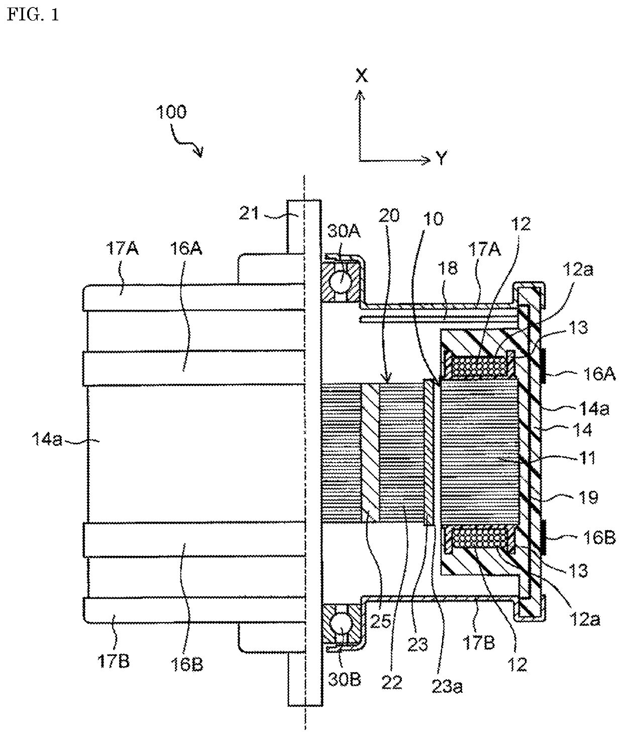
[0065]FIG. 1 is a half cross-sectional view schematically showing a configuration of a molded motor in a first exemplary embodiment of the present invention. Note that in the following description, the direction (X direction) along a rotary shaft of a motor is referred to as a “shaft direction”, the radial direction (Y direction), centering on the rotary shaft is referred to as a “radial direction”, and the direction circling around the rotary shaft as a center is referred to as a “circumferential direction”.

[0066]As shown in FIG. 1, molded motor 100 in the present exemplary embodiment includes: rotor 20; and stator 10 disposed, on an outer side of rotor 20 in the radial direction, to face rotor 20. Note that in molded motor 100 in the present exemplary embodiment, there is embedded circuit board 18 on which a circuit to control driving of the motor is mounted.

[0067]Stator 10 has: stator core 11 which is constituted by a plurality of metallic sheets laminated along the shaft directi...

second exemplary embodiment

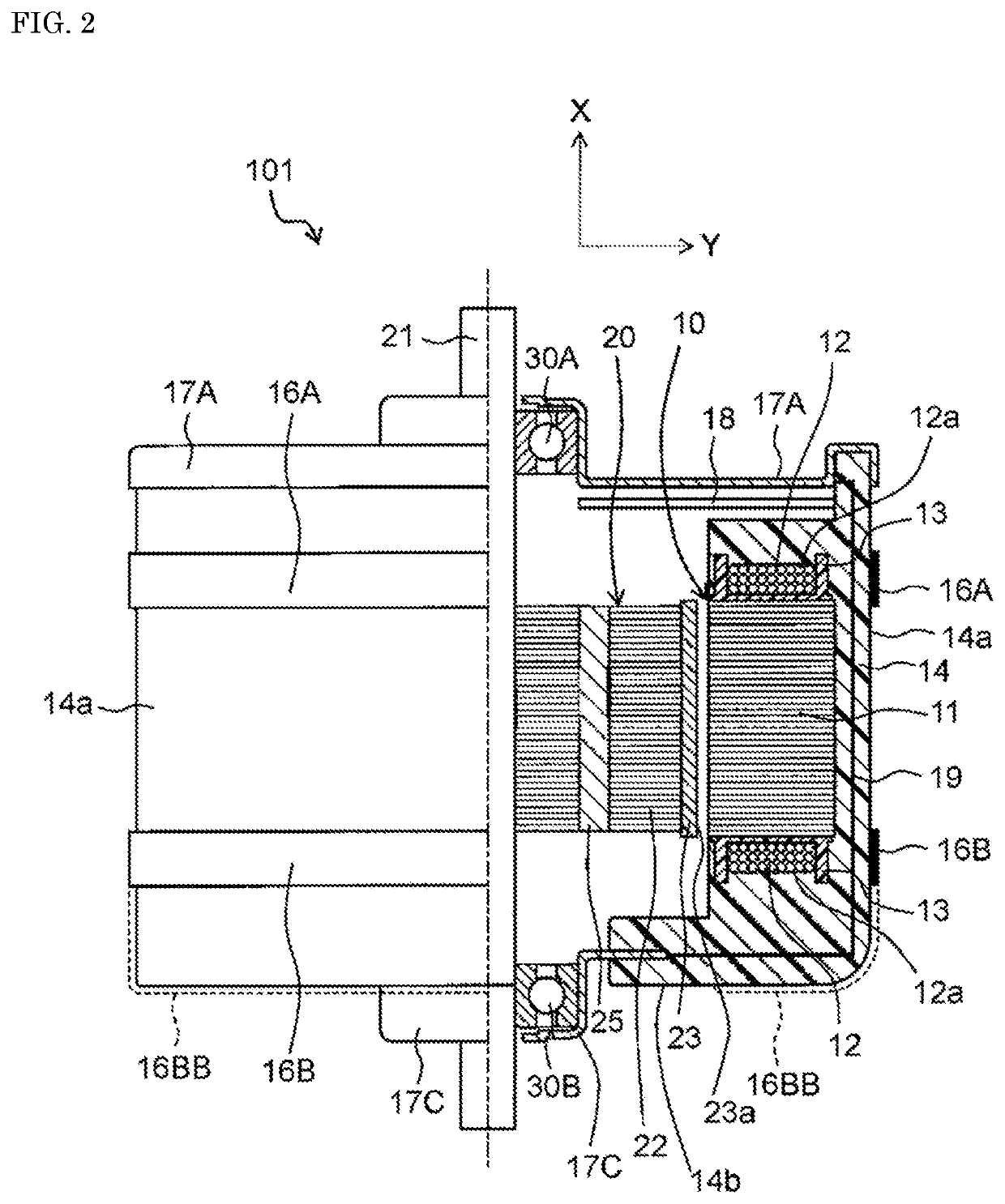
[0082]FIG. 2 is a half cross-sectional view schematically showing a configuration of molded motor 101 in a second exemplary embodiment of the present invention. Note that in molded motor 101 in the present exemplary embodiment, configurations of a pair of metal brackets 17A, 17C and molding resin 14 are different from the configurations in the first exemplary embodiment, but the other configurations are the same as in the first exemplary embodiment. In the following description, the components that are the same as the components having been once described are assigned the same reference marks, and the corresponding descriptions are used.

[0083]As shown in FIG. 2, in the present exemplary embodiment, lengths of outer peripheral diameters of the pair of metal brackets 17A, 17C are different from each other. Specifically, metal bracket 17A that fixes an outer ring of shaft bearing 30A has an outer peripheral diameter that is almost the same as an outer peripheral diameter of molding res...

modified example

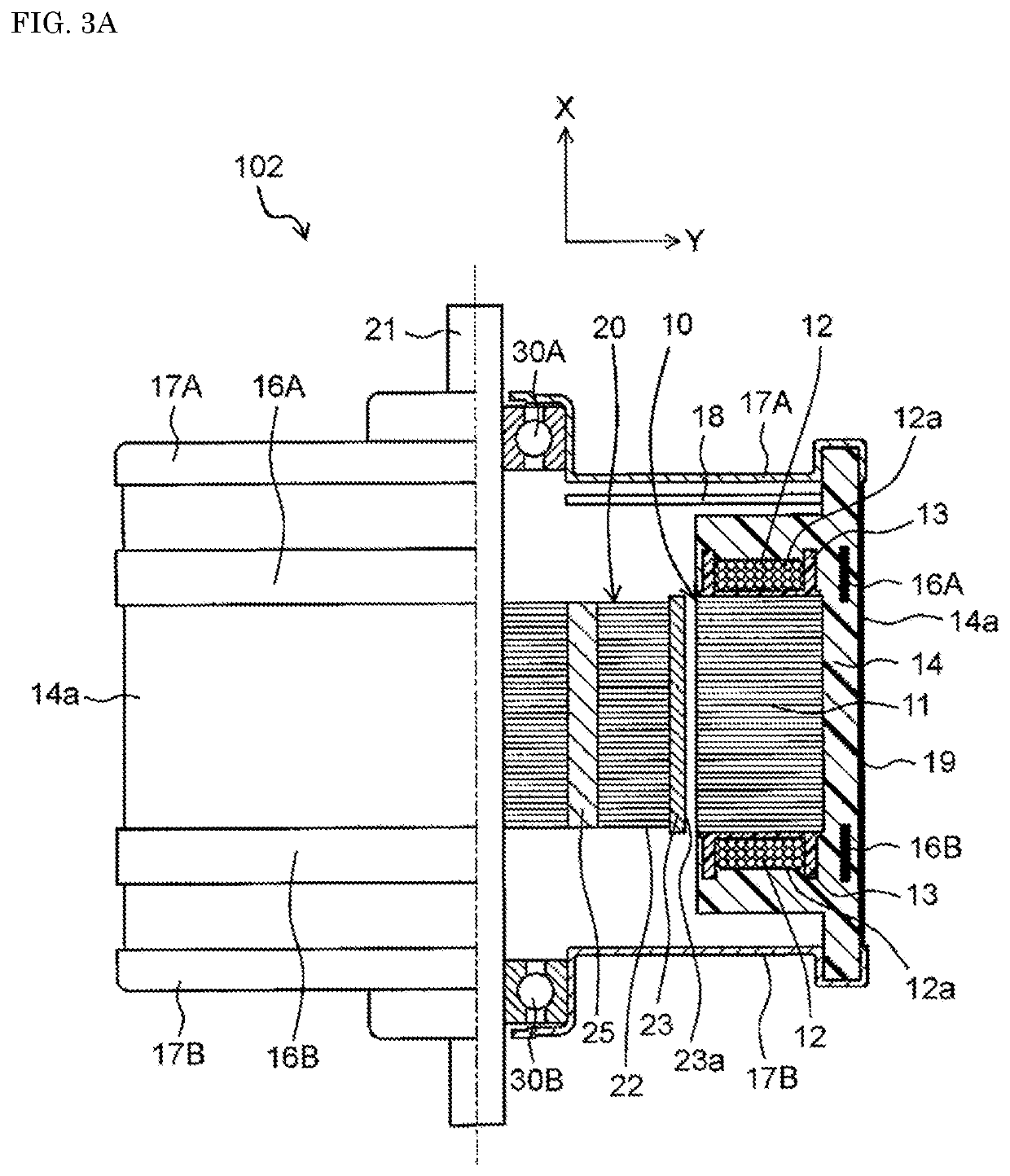
[0090]FIGS. 3A and 3B are half cross-sectional views each schematically showing a configuration of a molded motor in a modified example of the present invention. In the above exemplary embodiments, as shown in FIGS. 1, and 2, metal members 16A, 16B are disposed on outer surface 14a of molding resin 14; however, as molded motor 102, metal members 16A, 16B may be embedded in molding resin 14 as shown in FIG. 3A.

[0091]Further, in the above exemplary embodiments, as shown in FIGS. 1 and 2, conductive member 19 is disposed in molding resin 14; however, conductive member 19 may be disposed on outer surface 14a of molding resin 14, as shown in FIG. 3A.

[0092]In the above, the present invention is described based on the exemplary embodiments, but the above description does not limit the invention, and various modifications can, of course, be made. For example, in the above exemplary embodiments, metal members 16A, 16B each having a belt shape are provided apart from each other on outer surfa...


PUM


Abstract

A molded motor of the present invention includes a rotor, a stator, a pair of shaft bearings, a pair of metal brackets, and a molding resin. The rotor has: a rotary shaft extending in a shaft direction; and a rotary body that has a permanent magnet and is fixed to the rotary shaft. The stator has: a stator core on which a plurality of salient poles are formed; and a plurality of coils each wound on each salient pole via an insulator, where the stator is covered by the molding resin and is disposed to face the rotor. The pair of metal brackets each fix each of the shaft bearings, and the shaft bearings rotatably support the rotor. Further, the rotary body has a dielectric layer formed between the rotary shaft and an outer peripheral surface of the rotary body. A metal member is provided, on an outer peripheral side of a coil end of the coil and on at least a part facing the coil end, in a circumferential direction.

Description

CROSS-REFERENCE TO RELATED APPLICATIONS[0001]This application is a U.S. national stage application of the PCT International Application No. PCT / JP2018 / 006978 filed on Feb. 26, 2018, which claims the benefit of foreign priority of Japanese patent application 2017-037229 filed on Feb. 28, 2017, the contents all of which are incorporated herein by reference.TECHNICAL FIELD[0002]The present invention relates to a molded motor whose stator is covered with a molding resin.BACKGROUND ART[0003]When a brushless DC motor is driven by an inverter using a pulse width modulation method (hereinafter, referred to as a “PWM method”), a neutral point potential of a winding wire is not zero. Therefore, a voltage difference occurs between an outer ring of a shaft bearing and an inner ring of the shaft bearing (hereinafter, this voltage difference is also referred to as a “shaft voltage”). There is a problem that if this shaft voltage exceeds a breakdown voltage of an oil film in the shaft bearing, a d...

Claims


Application Information

Patent Timeline
Patent Type & Authority Patents(United States)
IPC IPC(8): H02K11/40H02K1/04H02K1/14H02K1/27H02K5/173H02K7/08H02K21/16H02K5/136H02K5/08H02K5/02
CPCH02K1/04H02K1/146H02K1/276H02K1/278H02K5/02H02K5/08H02K5/136H02K5/1732H02K7/083H02K21/16H02K11/40H02K11/20Y02T10/64
Inventor YAMAGATA, YOSHIKAZUWATANABE, AKIHIKOAMAYA, TAKANORINANBU, YASUOKATO, HISAAKIWAKAMORI, YASUNORITANIGUCHI, MASAYUKI
Owner PANASONIC INTELLECTUAL PROPERTY MANAGEMENT CO LTD
Why Eureka
Try Eureka