Monitoring an Explosive Device

a technology of explosive devices and monitoring devices, which is applied in the direction of survey, drilling machines and methods, and well accessories, etc., can solve the problems of multiple failed attempts to activate explosive devices, unnecessarily affecting the safety of personnel, and unacceptably high system failure rate of individual subsystems

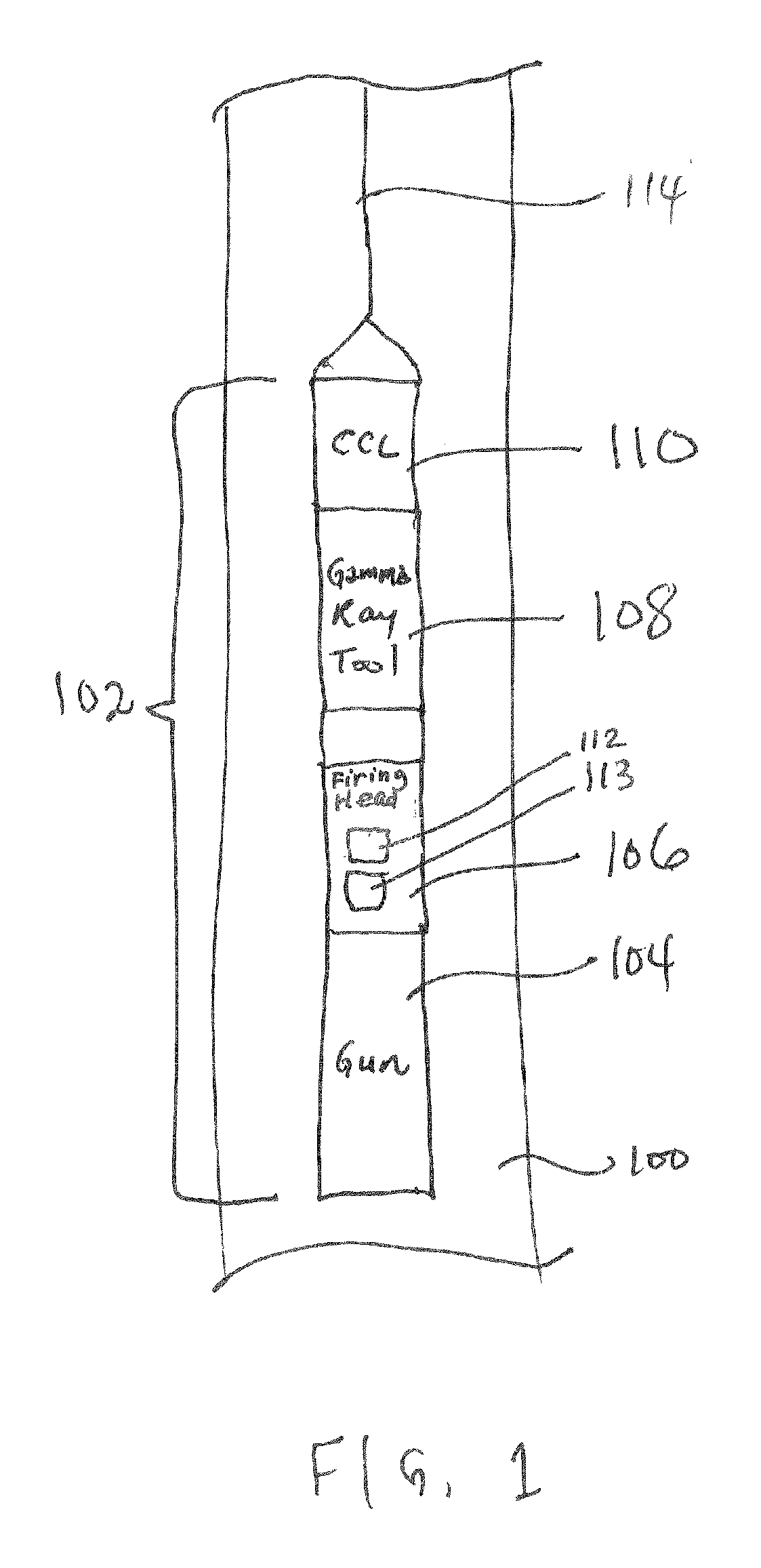
Active Publication Date: 2007-06-07
SCHLUMBERGER TECH CORP
View PDF18 Cites 57 Cited by
  • Summary
  • Abstract
  • Description
  • Claims
  • Application Information

AI Technical Summary

Problems solved by technology

While each subsystem has been designed to achieve a target reliability level, the collection of the individual subsystems may produce an unacceptably high system failure rate.
In particular, the electrical transmission path (from the earth surface down to the explosive device located downhole in the wellbore) presents particular difficulties, as failure mechanisms can be difficult to isolate, leading to multiple failed attempts at activating the explosive devices before the root cause is isolated and resolved.
This problem is especially acute in the case of intermittent failures (such as due to short circuits), which may be present while the equipment is deployed downhole, but then disappear when the tools are brought to the more benign conditions of the earth surface for troubleshooting.
Equipment may often be replaced and classified as defective unnecessarily when the fault disappears for an unrelated reason.
However, performing such a test at the earth surface is hazardous due to possible inadvertent detonation of the explosive device at the earth surface.
However, such relatively sophisticated equipment are associated with relatively high costs that may not be practical in many situations.

Method used


Image

  • Monitoring an Explosive Device
  • Monitoring an Explosive Device
  • Monitoring an Explosive Device

Examples


Embodiment Construction

[0012] In the following description, numerous details are set forth to provide an understanding of the present invention. However, it will be understood by those skilled in the art that the present invention may be practiced without these details and that numerous variations or modifications from the described embodiments may be possible.

[0013] As used here, the terms “up” and “down”; “upper” and “lower”; “upwardly” and downwardly”; “upstream” and “downstream”; “above” and “below”; and other like terms indicating relative positions above or below a given point or element are used in this description to more clearly describe some embodiments of the invention. However, when applied to equipment and methods for use in wells that are deviated or horizontal, such terms may refer to a left to right, right to left, or other relationship as appropriate.

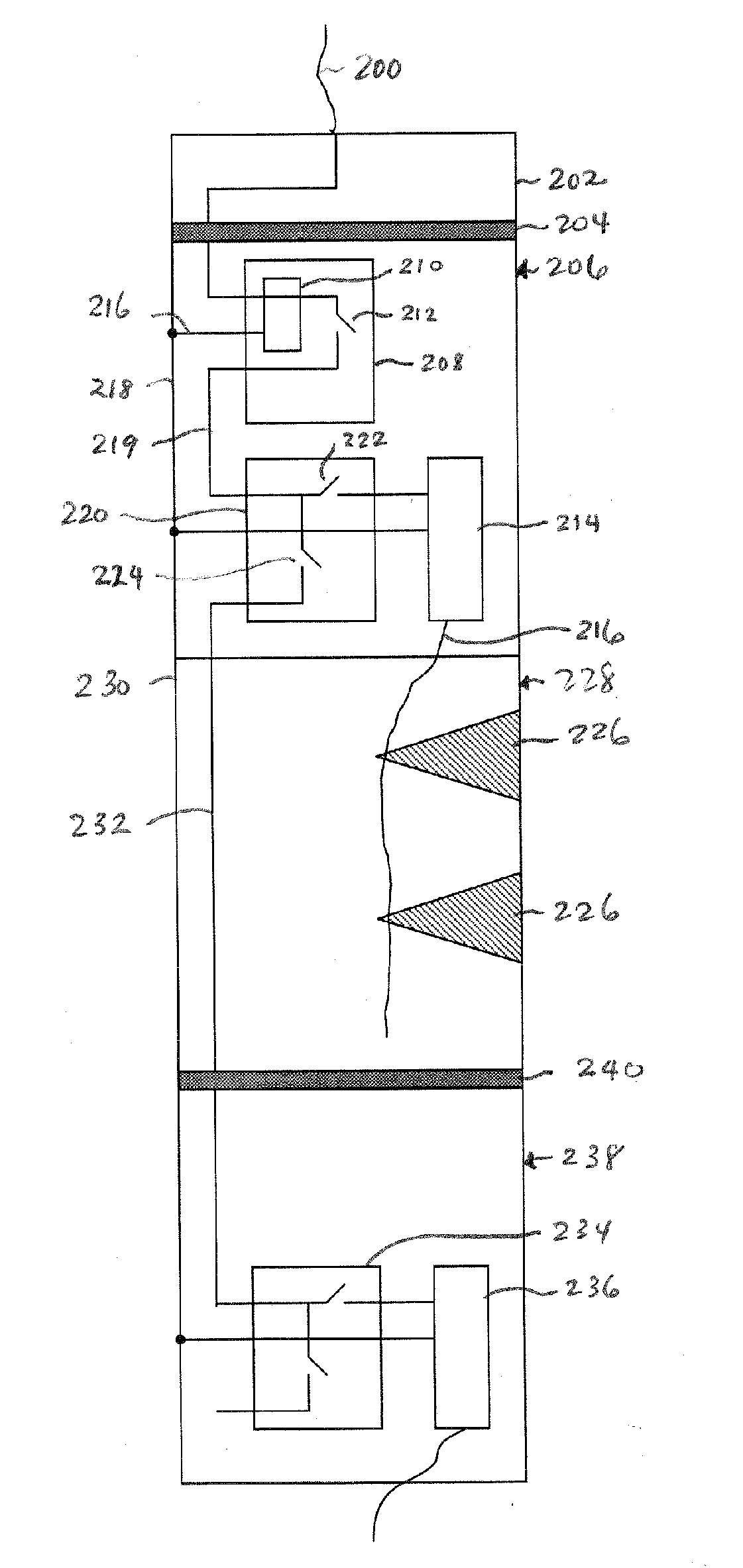
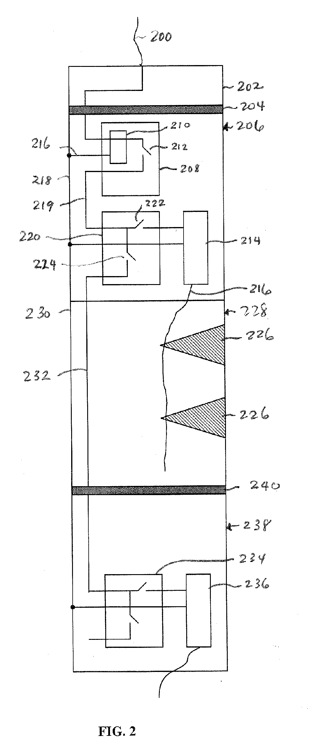
[0014] According to some embodiments, a monitor is provided within a housing of an explosive device to verify the integrity of a stimulus ...


PUM


Abstract

An explosive device includes a housing, and at least one of an initiator and an explosive in the housing. The at least one of the initiator and explosive are activatable in response to stimulus from a control line. A monitor in the housing monitors a state of the stimulus to enable determination of a status of the explosive device.

Description

TECHNICAL FIELD [0001] The invention relates generally to monitoring an explosive device. BACKGROUND [0002] In completing a well, various operations are performed in the wellbore, including operations in which explosive devices are detonated. Examples of explosive devices include perforating guns, pipe cutters, tools for setting packers, and so forth. [0003] Activating an explosive device in a wellbore relies on the fault-free operation of a relatively complex collection of individual subsystems. While each subsystem has been designed to achieve a target reliability level, the collection of the individual subsystems may produce an unacceptably high system failure rate. In particular, the electrical transmission path (from the earth surface down to the explosive device located downhole in the wellbore) presents particular difficulties, as failure mechanisms can be difficult to isolate, leading to multiple failed attempts at activating the explosive devices before the root cause is is...

Claims


Application Information

Patent Timeline
Patent Type & Authority Applications(United States)
IPC IPC(8): E21B43/11
CPCE21B43/116E21B43/11857F42D1/045
Inventor GEREZ, DAVIDDA GAMA, CESAR
Owner SCHLUMBERGER TECH CORP
Why Eureka
Try Eureka