Subsea valve actuator and method

Inactive Publication Date: 2000-03-28
WORLDWIDE OILFIELD MACHINE
View PDF16 Cites 106 Cited by
  • Summary
  • Abstract
  • Description
  • Claims
  • Application Information

AI Technical Summary

Problems solved by technology

As water depth increases, increased hydrostatic head, or ambient sea pressure, creates forces on the valves and actuators that due to a combination of conditions can unreasonably delay or preclude fail-safe operation upon loss of hydraulic control pressure.
The valve size and internal valve line pressure can create additional problems under such conditions.
As well, the hydraulic fluid volume and pressure may be limited due to typical system components that may include a hydraulic fluid accumulator and/or a hydrostatically pressurized subsea hydraulic fluid reservoir to avoid the need for multiple hydraulic lines to the surface.
Furthermore, subsea actuators need to be very reliable because they operate in an environment that is not readily accessible.
Conventional subsea actuators often have numerous problems that limit the operational range, reliability, cost, and maintenance thereof.
While there are several commercially available subsea actuators on the market with different designs, the problems tend to be related.
While this arrangement may afford sufficient spring strength for actuation to depths of 1000 feet or so, it results in numerous problems for deep water subsea actuators.
It is generally not desirable to increase the size of the hydraulic cylinder to provide a more powerful spring because this also increases the amount of hydraulic fluid necessary for operation an

Method used


Image

  • Subsea valve actuator and method

Examples


Embodiment Construction

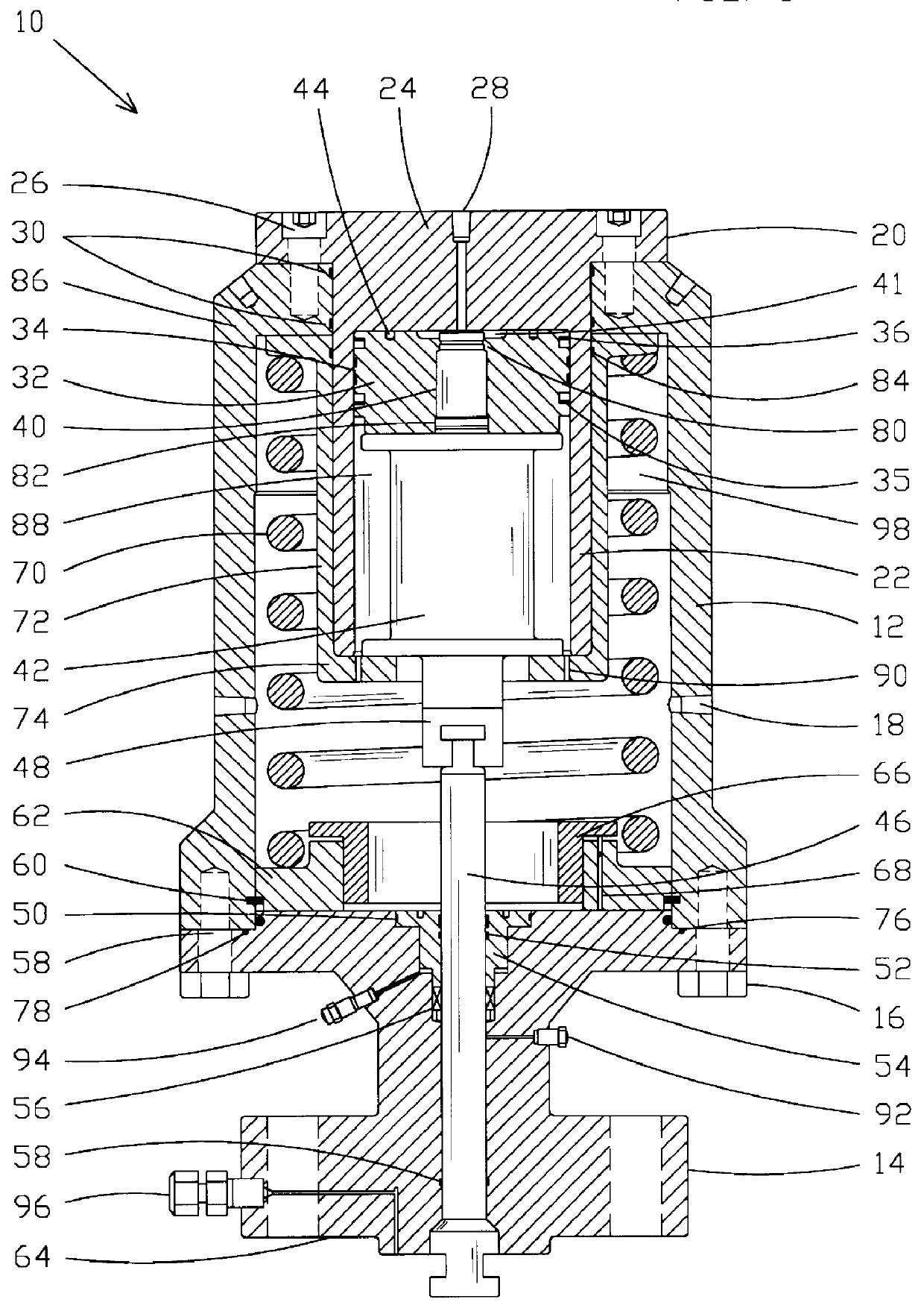
Referring now to the drawings, and more particularly to FIG. 1, the generally preferred configuration of subsea actuator 10, in accord with the present invention, is illustrated.

FIG. 1 shows actuator housing 12 removably connected to gate valve bonnet 14 preferably be means of bolts such as hex head bolt 16 although other removable fasteners, such as various types of bolts or clamps could also be used. Hydraulic ports 18, which may be 1 / 2 inch NPT ports preferably including at least two such ports 180.degree. apart, may are formed in actuator housing 12. Other numbers and spacings or sizes of hydraulic ports could be used as desired to provide connections for the assist line hydraulic control that is used in subsea systems for compensation of the subsea environment hydrostatic head. The unique means of the present invention for connecting assist line hydraulic fluid to an internally positioned hydraulic cylinder 20 is discussed hereinafter.

Hydraulic cylinder 20 includes and is prefe...


PUM


Abstract

A subsea actuator and method is disclosed that includes a removable monolithic cap/hydraulic chamber that seals the actuator housing top with seals placed around the monolithic cap, defines a straight hydraulic line and port for control line hydraulic fluid, and provides for fasteners to secure the top of the subsea actuator. The monolithic cap/hydraulic chamber is so limited in metal and machine time that it can be a throw-away maintenance item. A preferably cup-shaped spring lifter is provided in telescoping relationship to the hydraulic chamber. Several short hydraulic fluid passageways are provided in the bottom cup portion of the spring lifter to permit assist hydraulic control fluid into the hydraulic chamber below the piston. The driving stem provides a removable connection to the hydraulic piston from the top of the actuator housing and a quick disconnect permits disconnection of the driving stem from the valve stem. The high tension spring does not need to be removed to perform maintenance, and all wear items and seals are readily accessible. Change or replacement of the stem packing is made from the top of the bonnet to avoid dissasembling the bonnet to valve body connection. The spring chamber within the actuator housing may be increased in size to accommodate a larger spring as necessary for fail-safe operation without changing the size of the hydraulic chamber. All sliding components ride on wear rings to increase the lifetime of reliable subsea operation. The moving components are mounted in a compact, concentric configuration.

Description

1. Field of the InventionThe present invention relates generally to subsea gate valve actuators and, more particularly, to apparatus and methods for a fail-safe hydraulic subsea actuator that reliably operates in deep water for extended time periods.2. Description of the BackgroundRemote subsea fail-safe gate valves are typically controlled with hydraulic actuators. The hydraulic actuators and often their controls are located on the ocean floor. Although the location, configuration and types of actuators and controls vary, their operation is subjected to ambient sea pressure whether the actuator and controls are an open or closed system. The time required for a fail-safe valve to fail-safe close is critical, and therefore a short response time is highly desirable. As water depth increases, increased hydrostatic head, or ambient sea pressure, creates forces on the valves and actuators that due to a combination of conditions can unreasonably delay or preclude fail-safe operation upon ...

Claims


Application Information

Patent Timeline
IPC IPC(8): E21B34/00E21B34/04F16K31/122
CPCE21B34/04F16K31/1221Y10T137/6089Y10T137/6011Y10T137/0514
Inventor CHATUFALE, VIJAY R.
Owner WORLDWIDE OILFIELD MACHINE
Why Eureka
Try Eureka