High resolution surveillance camera

a high-resolution, surveillance camera technology, applied in the scanning details of the television system, the television system, instruments, etc., can solve the problems of inability to provide such imagery, inability to know what to photograph, and inability to appreciate the meaning of images later

Inactive Publication Date: 2007-06-07
IMMERSIVE VENTURES
View PDF31 Cites 21 Cited by
  • Summary
  • Abstract
  • Description
  • Claims
  • Application Information

AI Technical Summary

Benefits of technology

[0006] In contrast, the at least one line scan sensor in a camera of the present invention is arranged to be not parallel to the axis of rotation. For example, the at least one line scan sensor may be perpendicular to, or at an acute angle to, the axis of rotation. As a result, the rotation of the line scan sensor allows high-resolution multi-frame (e.g., motion) images to be formed for a much larger image area than conventional closed circuit television cameras.

Problems solved by technology

In chaotic situations it is difficult to know what to photograph.
But too often the meaning of images can only be appreciated later.
Conventional imaging systems and technologies are incapable of providing such imagery because they lack the ability to persistently image such large areas and the ability to process the vast amounts of image data that would arise from such imagery.
The reason is that the numbers of cameras and images that would be required to capture all of an urban core, for example, would be prohibitive.
The various camera images are scattered, and not able to be presented as a unified picture.

Method used


Image

  • High resolution surveillance camera
  • High resolution surveillance camera
  • High resolution surveillance camera

Examples


Embodiment Construction

[0015] In the discussion that follows, terms such as “persistent surveillance system” to refer to sample implementations of the present invention. However, no particular limitation should be inferred in the scope or applicability of the invention from use of this term.

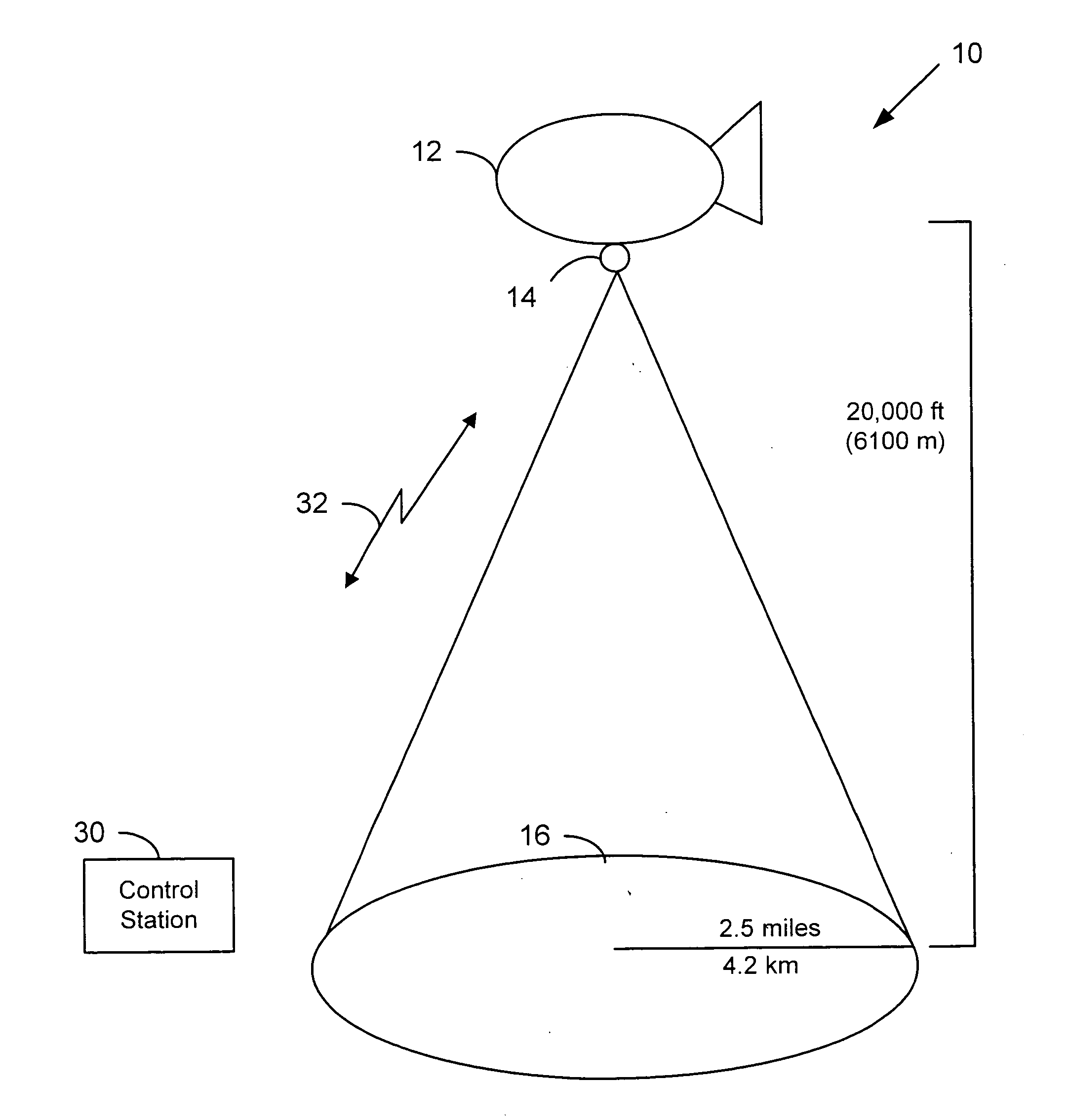
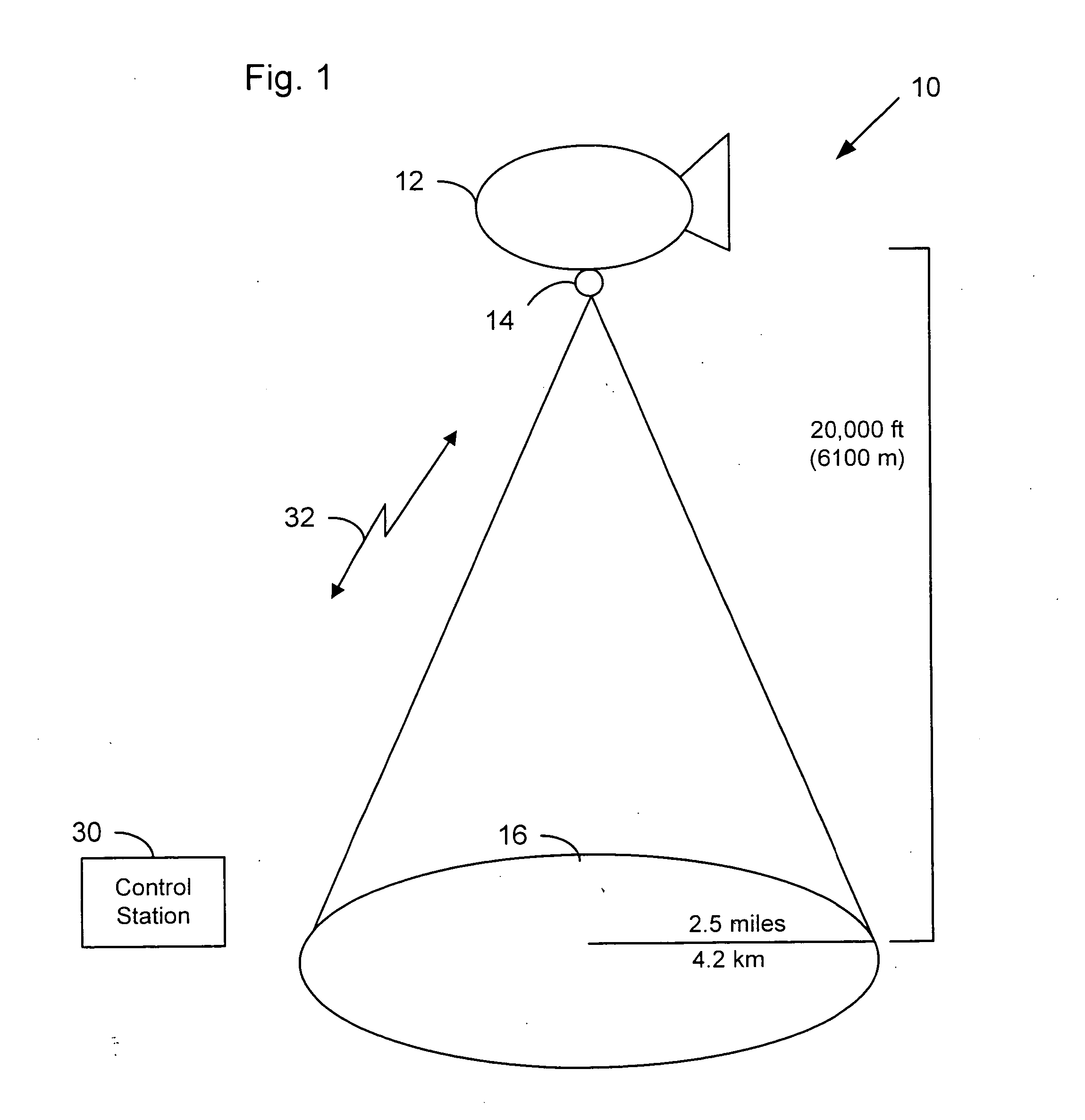
[0016] The present invention features a repeated high-resolution scanning of a wide area from a fixed position. FIG. 1 illustrates a high-resolution persistent surveillance system of a wide area 10 according the present invention. The persistent surveillance system 10 includes a persistent airborne platform such as a stabilized aerostat, blimp, dirigible or tethered balloon, referred to as a blimp 12, which supports a downward-looking high resolution surveillance camera system 14.

[0017] This high resolution camera system 14 continuously images a large surveillance area 16 of multiple square miles at a resolution capable of discerning vehicles and individual human beings. In one example implementation, surveillance ar...


PUM


Abstract

A surveillance device makes use of a fixed point in space such as a stabilized blimp, and a downward-looking high-resolution scanning camera. One or more line scan devices are arranged in a radial fashion on a rotating disk, together with associated lenses, so as to repeatedly scan an area of interest. To allow for manageable data bandwidth and to focus on objects of interest, the data from successive scans is compared so as to show primarily the moving objects, with occasional full-scan reference images included.

Description

FIELD OF THE INVENTION [0001] This invention generally relates to digital imaging systems, and in particular to such a system that employs rotary line scanning and reduction of non-essential image elements to provide a high-resolution surveillance system. BACKGROUND AND SUMMARY OF THE INVENTION [0002] In chaotic situations it is difficult to know what to photograph. It is easy to miss an essential element. If a crime has been committed, it is even more important to gather crucial evidence. But too often the meaning of images can only be appreciated later. Therefore the best forensic analysis would allow one to see a total picture of the essential elements and also be able to trace the most important ones after the fact. In combating an insurgency in an urban area, for example, it would be desirable to continuously image all of an area over which insurgency events might occur, so as to have the ability to trace back from such an event any movements or actions that led up to it. Conve...

Claims


Application Information

Patent Timeline
Patent Type & Authority Applications(United States)
IPC IPC(8): H04N7/18
CPCG01C11/02G08B13/19626G08B13/1963G08B13/19641H04N3/1581H04N25/701
Inventor MCCUTCHEN, DAVID
Owner IMMERSIVE VENTURES
Why Eureka
Try Eureka