
Motion-compensated inverse filtering with band-pass filters for motion blur reduction

a motion blur reduction and band-pass filter technology, applied in the field of motion blur reduction, can solve the problems of increasing the market share of crt, lcd performance much worse, and the performance of active matrix liquid crystal displays (am-lcds) is much worse, so as to reduce the motion blur of images

Inactive Publication Date: 2007-06-07
KONINKLIJKE PHILIPS ELECTRONICS NV
View PDF9 Cites 31 Cited by
  • Summary
  • Abstract
  • Description
  • Claims
  • Application Information

AI Technical Summary

Benefits of technology

[0033] In view of the above-mentioned problem, it is, inter alia, an object of the present invention to provide improved methods, computer programs, computer program products and devices for reducing motion blur of images of a video signal shown on a hold-type display.

Problems solved by technology

In particular, active-matrix liquid crystal displays (AM-LCDs) have increased in performance and decreased in price so dramatically, that the market share of the CRT is decreasing at a rapid pace.
In that area, LCDs perform much worse, since the LC-molecules that provide the basic display effect react slowly to image changes.
This causes an annoying smearing (blurring) of moving objects, which makes the LCD unsuited for video applications.
Therefore, a lot of effort has been put into speeding up the response of LC materials.
However, speeding up the response of LC materials to lower values is not enough to completely avoid motion blur.
It is well known that this prolonged light emission does not match very well with the way humans perceive moving images.
This ‘point spreading’ results in a loss of sharpness of moving objects.
This assumption is not always true, which leads to one of the most widely known artifacts in display systems: large area flicker.
However, even these will still have a light emission during the whole frame period due to the sample-and-hold behavior of the active matrix and the continuous illumination by the backlight.
Although the temporal “hold” aperture is beneficial with respect to large area flicker, it will cause a spatial blurring of moving objects on the retina of the viewer.
(11)), e.g. below noise thresholds, can not realistically be achieved.
However, in flat (undetailed) image parts, the motion estimator has a high probability of estimating the wrong motion vector that determines the cut-off frequency of the spatial frequency enhancement filter, resulting in undesirable noise amplification at high spatial frequency enhancement filter gains, which significantly degrade the quality of the images of the video signal.

Method used


Image

  • Motion-compensated inverse filtering with band-pass filters for motion blur reduction
  • Motion-compensated inverse filtering with band-pass filters for motion blur reduction
  • Motion-compensated inverse filtering with band-pass filters for motion blur reduction

Examples


Embodiment Construction

[0086] The present invention sets out from the observation that the display+eye filter Hf({right arrow over (f)}x) of Eq. (11), as illustrated in FIG. 8, at high speeds has a considerable attenuation at already very low spatial frequencies. Furthermore, it is recognized that the human visual system is more sensitive to the lower spatial frequencies, and that the higher frequencies generally have a lower signal-to-noise ratio. Furthermore, the present invention recognized that in common video material, moving objects will not contain the highest frequencies due to the limitations of the camera (camera blur). For this reason, viewers are used to losing some detail at high speed, although not to the extent (up to lower spatial frequencies) that is caused by LCD panels.

[0087] According to the present invention, in case of high speeds, it is thus proposed to give priority to the compensation of the lowest affected frequencies, and to leave the highest frequencies basically unchanged. Th...


PUM


Abstract

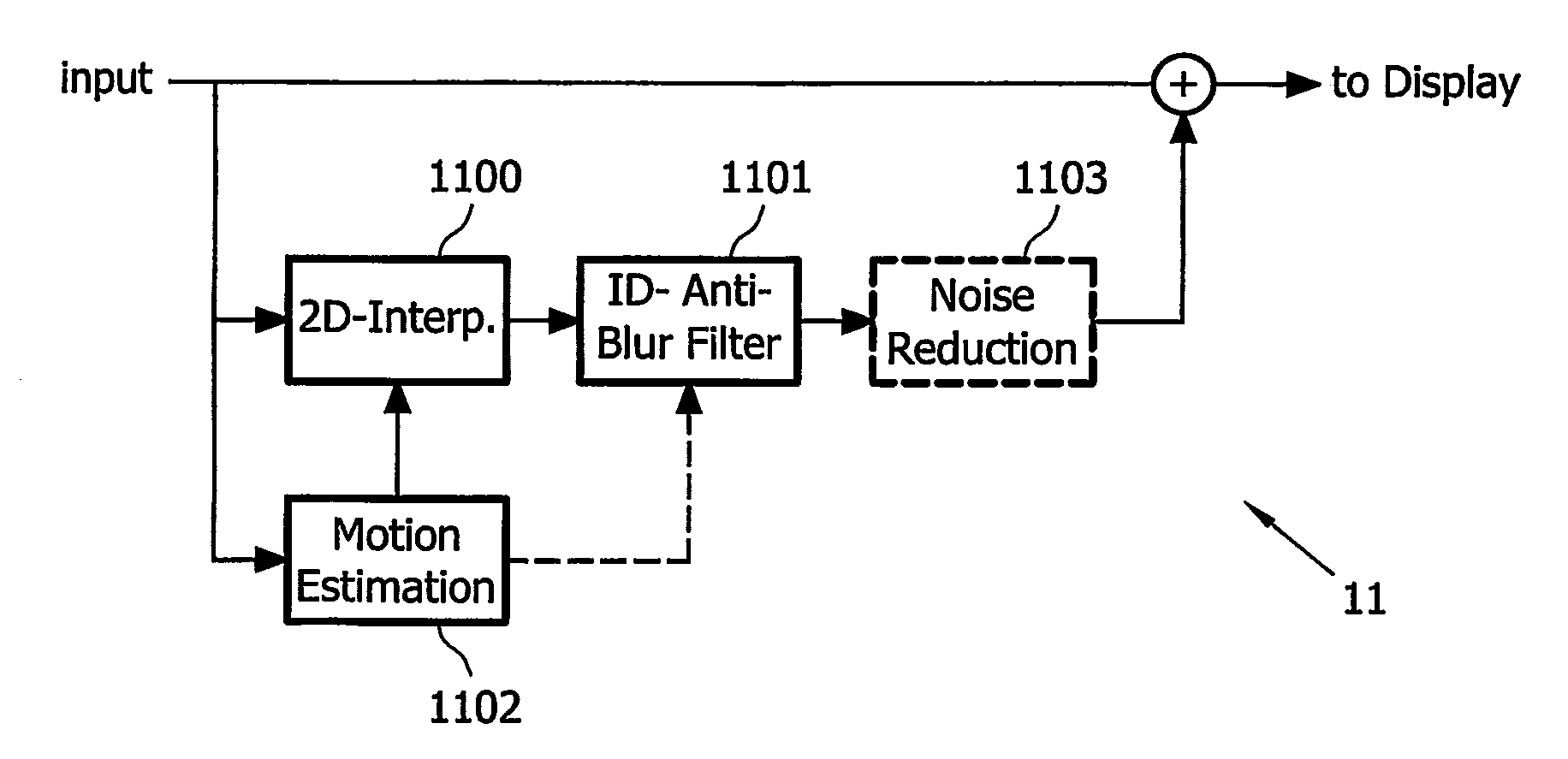
This invention relates to a method, a computer program, a computer program product, and a device for reducing motion blur of images of a video signal shown on a hold-type display (101), comprising estimating (1102) motion vectors of moving components in said images of said video signal; band-pass filtering (1100, 1101) said video signal with respect to a spatial frequency domain, wherein said band-pass filtering at least partially depends on said estimated motion vectors, and wherein with increasing length of said estimated motion vectors, the passband of said band-pass filtering adaptively shifts from high spatial frequencies to medium spatial frequencies; and combining (1104) said video signal and said band-pass filtered video signal to produce an input video signal for said hold-type display.

Description

FIELD OF THE INVENTION [0001] This invention relates to a method for reducing motion blur of images of a video signal shown on a hold-type display. BACKGROUND OF THE INVENTION [0002] Over the last years, the traditional cathode ray tube (CRT) display has had to face increasing competition from alternative display principles, which are mainly based on active-matrix technology. In particular, active-matrix liquid crystal displays (AM-LCDs) have increased in performance and decreased in price so dramatically, that the market share of the CRT is decreasing at a rapid pace. The main differentiating feature of these new display principles is their size: LCDs are thin, flat and lightweight. This has enabled the first market for these displays: laptop computers. By now, the LCD has also almost taken over the desktop monitor market, where not only its size has made the difference, but also its uniform, sharp, and flicker-free picture reproduction. Nowadays, the CRT is also having to face com...

Claims


Application Information

Patent Timeline
IPC IPC(8): H04N11/00H04N5/21
CPCH04N5/21
Inventor KLOMPNHOUWER, MICHIEL ADRIAANSZOONVELTHOVEN, LEO JAN
Owner KONINKLIJKE PHILIPS ELECTRONICS NV
Learn More