
Rake reception device and rake reception method

a technology of a receiving device and a receiving device, which is applied in the direction of transmission, electrical equipment, etc., can solve the problems of many unused fingers in the receiving device, and the receiver provided with the conventional cdma receiving apparatus cannot allocate the appropriate number of fingers per channel

Inactive Publication Date: 2007-06-07
PANASONIC CORP
View PDF5 Cites 29 Cited by
  • Summary
  • Abstract
  • Description
  • Claims
  • Application Information

AI Technical Summary

Benefits of technology

[0006] It is an object of the present invention to provide a RAKE receiving apparatus and RAKE receiving method capable of allocating an appropriate number of fingers to a channel.

Problems solved by technology

This causes a problem that RAKE receiver provided with the conventional CDMA receiving apparatus cannot allocate the appropriate number of fingers per channel according to communication conditions.
As a result, this causes a problem that there are many unused fingers in CDMA receiving apparatus.

Method used


Image

  • Rake reception device and rake reception method
  • Rake reception device and rake reception method
  • Rake reception device and rake reception method

Examples


Embodiment Construction

[0015] It is a feature of the present invention to make variable number of fingers which are allocated to the received channel according to communication conditions.

[0016] Embodiments of the present invention will now be described in detail with reference to the accompanying drawings.

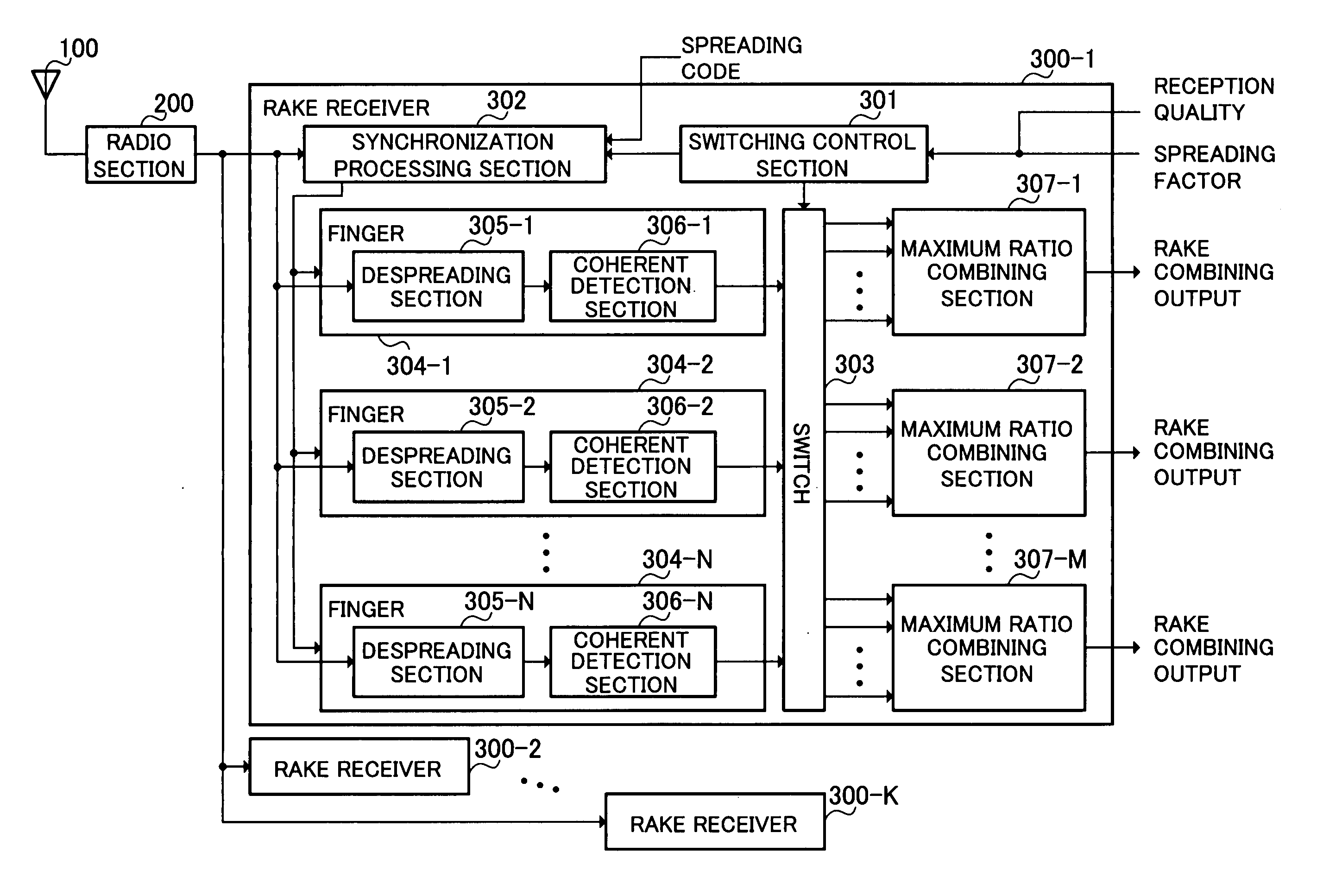
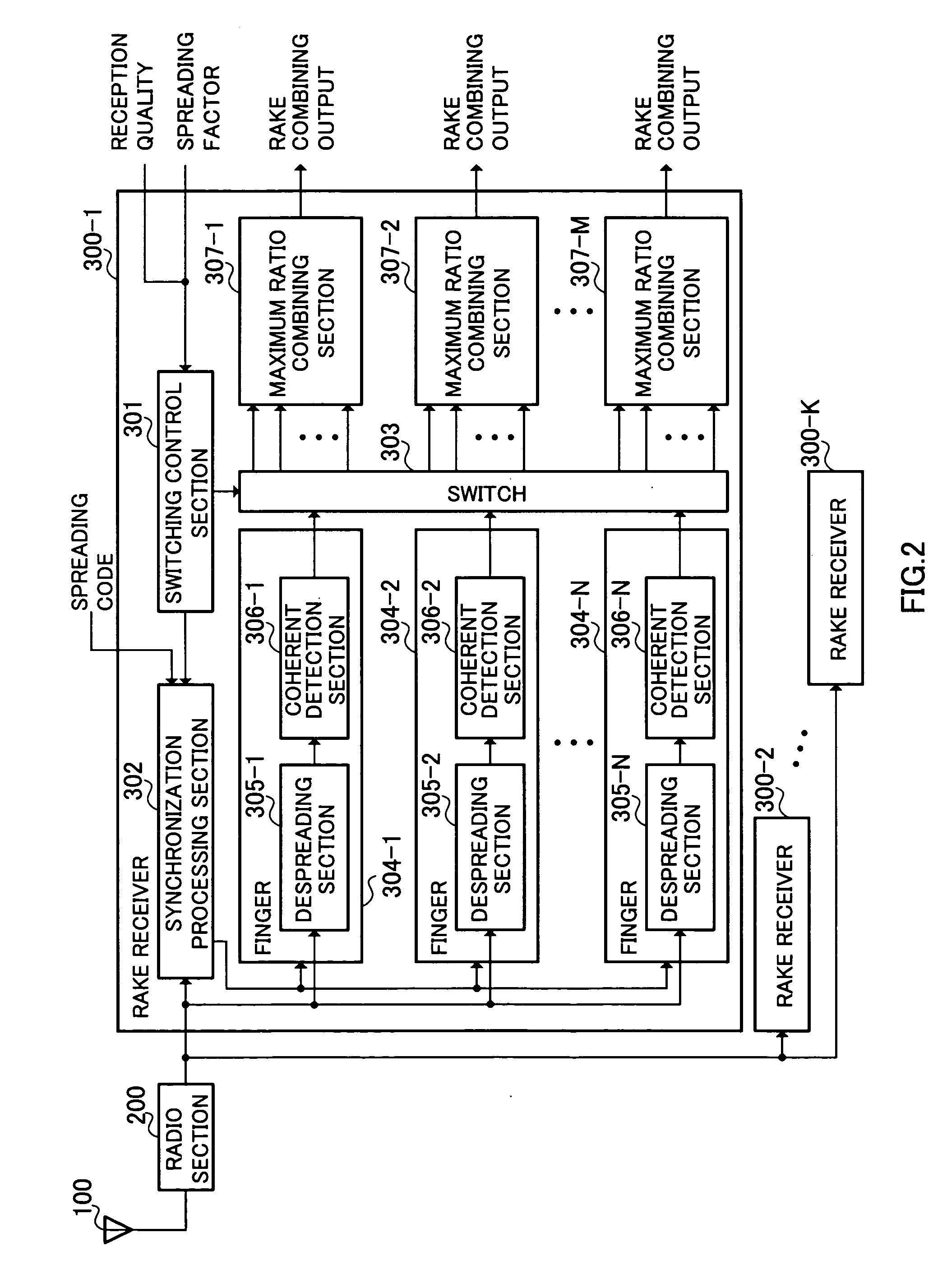
[0017]FIG. 2 is a block diagram showing a configuration of CDMA receiving apparatus according to an embodiment of the present invention.

[0018] The CDMA receiving apparatus shown in FIG. 2 is configured with antenna 100, radio section 200 that down-converts a RF signal received at antenna 100 via a channel to a baseband signal (received signal), and a plurality (for example, K) of RAKE receivers 300-1, 300-2, . . . , and 300-K that perform RAKE reception of received signals. Since RAKE receivers 300-1, 300-2, . . . , and 300-K all have the same configuration, an arbitrary RAKE receiver will be indicated as “300.”

[0019] RAKE receiver 300 has switching control section 301, synchronization processing sec...


PUM


Abstract

A RAKE reception device capable of allocating an appropriate number of fingers to a channel. In this device, a selection control section (301) sets a finger (304) allocated to the channel from the channel communication state and a control signal based on this setting is output to a synchronization processing section (302) and to a selection switch (303). According to the control signal, the synchronization processing section (302) detects a path and a spread code phase in a reception signal and allocates the detected path to the finger (304) which has been set. The finger (304) which has been set de-spreads the signal of the path allocated and performs coherent detection. According to the control signal, the selection switch (303) switches the connection between the finger (304) and a maximum ratio combining section (307) so that the output from the finger (304) is output to the maximum ratio combining section (307).

Description

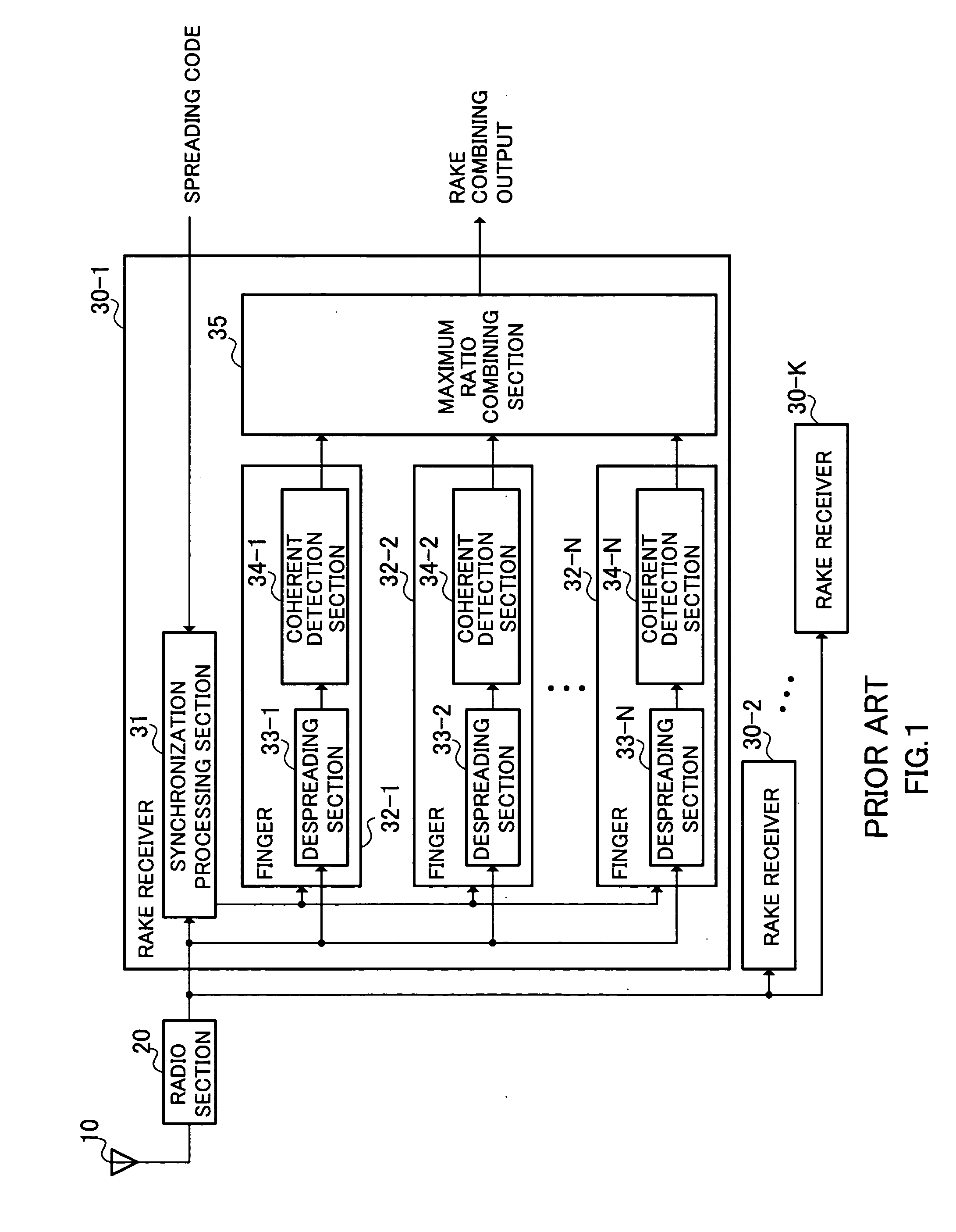
TECHNICAL FIELD [0001] The present invention relates to a RAKE receiving apparatus and RAKE receiving method. BACKGROUND ART [0002] CDMA (Code Division Multiple Access) receiving apparatus is used in mobile communication system such as automobile telephones and cellular telephones, and adopts CDMA scheme for radio access scheme. Such CDMA receiving apparatus identifies a channel on a radio channel by a spreading code. Abase station equipped with such CDMA receiving apparatus generally performs RAKE reception for receiving and combining radio signals transmitted from a mobile station as a plurality of propagation paths. [0003]FIG. 1 is a block diagram showing a configuration of a conventional CDMA receiving apparatus. In FIG. 1, a RF (Radio Frequency) signal transmitted from the transmitting side via a channel is received at antenna 10, down-converted to a baseband signal (received signal) at radio section 20, and then RAKE reception is performed on a plurality (for example, K) of RA...

Claims


Application Information

Patent Timeline
IPC IPC(8): H04B1/00H04B1/707
CPCH04B1/7117H04B2201/70703H04B2201/7071
Inventor SATO, TAKAAKI
Owner PANASONIC CORP
Learn More